This thread has been locked.

If you have a related question, please click the "Ask a related question" button in the top right corner. The newly created question will be automatically linked to this question.

UCC28740: UCC28740 starts, but with certain sequence

Part Number: UCC28740

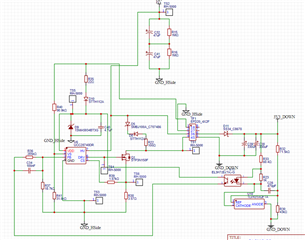
I have a flyback circuit made with a UCC28740. Originally the circuit has to put out 3.3 V but it doesn't start by itself. Doing some tests I have realized that I have managed to get it to start but with a strange sequence.
First I make a short circuit at the output, which keeps it at 0 V, then touching the VS pin of the UCC28740 with a screwdriver, the integrated starts, and I see at the output a consumption of 1.14 A, more or less the short current that it should have. Then I remove the short circuit condition and the circuit stays perfectly working.
I understand that shorting the output somehow by forcing the output to 0V keeps the output discharged, something that must be influencing although I don't really know what.

Then the VS pin if I do not understand what is happening, I do not know what physical phenomenon does with the screwdriver that produces the start of the integrated.

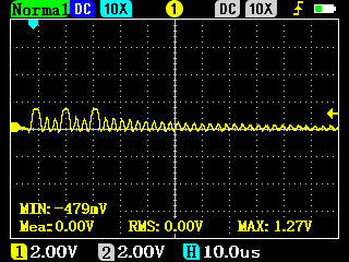
If I don't do any of this, the UCC28740 stays giving the three pulses in the DRV gate that are typical of the start.

  • Hi Alexis,

    I am taking care of this thread and I will be back to you tomorrow morning.

    Thank you

  • Hi Alexis,

    Please, take single shots in your oscilloscope of the waveforms I will indicate below. This will allow us to do a better debug process and solve the problem:

    -(VDD-GND): 5V/div or 10V/div. Put the trigger on this channel. Trigger: Rising, UVLO (21V). This waveform will let us know if VDD reaches UVLO and if the device is in fault mode. 

    -(VS-GND):  2V/div. This waveform will tell us if the device is starting up or switching.

    -(DRV-GND): 5V/div or 10V/div. This waveform will tell us if the IC is driving pulses to the main switch FET.

    -(CS-GND): 2V/div. This will show us the primary current.

    Time scale few ms/div (check what is the better scale when you catch the waveforms).

    Please, if possible, use Tip and Barrel connector when you probe (see pictures below), especially for (DRV-GND) and (VS-GND). These connectors allow better coupling and reduce parasitic inductances, allowing a very accurate probing and measurements.

    Thank you.

  • OK, I have taken the measures mentioned, although for safety reasons I preferred to take them without using a tip and barrel connector, although if absolutely necessary I could try it. 

    The signal (VDD-GND) according to the data sheet seems to indicate some kind of fault but it does reach the value of 21V.

    On VS-GND and other signals such as DRV-GND and CS-GND there is only one series of pulses, usually three, when UVLO is reached.

    the above image is VS-GND.

    In DRV-GND, the three pulses are better observed:

    The CS-GND signal my oscilloscope is unable to capture at 2V/div. Instead use a 1V/div scale. Here 7 to 8 pulses are observed:

  • Hi Alexis,

    Thanks for the waveforms. I will be back to you tomorrow morning.

    Thank you

  • Hi Alexis,

    -Looking the DRV pulses and CS waveforms it seems like the main switch FET is not turning on completely.

    -I took a look of your FET and STP3N150 is a 1500V, 2.5A, 6ohms with a total gate charge of 29.3nC. Why do you need a FET with such a high VDS voltage and gate charge? The big gate charge of your FET is not letting the gate driver of the IC to turn it on completely. This is reflected in your 5V pulses (it should be 10V or higher), the gate to source capacitor (Cgs) is so big that is not providing gate-source voltage and not letting the FET turn on completely, this will lead to a low current being pulled out from VS pin and not letting the device start. How much is your input voltage (HV in your schematic)? Depending on that voltage you can choose the VDS voltage of your FET. 

    If you are not sure how to choose your FET, I recommend using the Design Calculator Spreadsheet, you just input all your desired parameters like Input voltage range, output voltage range, switching frequency, among others (see example and link below). If you have any questions about the calculator, let me know.

    Thank you.

    Design Calculator: UCC28740 Design Calculator

  • Thanks for the reply.


    I originally used the design tool which suggested using IPD80R1K0CEBTMA1.
    From the design requirements we can expect an input voltage of 565-600 VDC. Due to the voltage produced at Toff on the flyback transformer it is normal to expect a VDS voltage of 700V on the transistor which the suggested FET would be correct, but considering the build quality of the transformer and that the coupling of the coils is usually not 100%, having a margin of only 100V did not seem like a safe option.
    Failing that I had to choose from a 1000 VGS or higher FET and in this case the STP3N150 was the one I had available.
    Also, looking at the spec sheet of the IPD80R1K0CEBTMA1, you can see that the gate charge is 31 nC which is more than the STP3N150.

    Where it does differ is that the IPD80R1K0CEBTMA1 has a lower resistance of 0.95 ohms and a VGSon of 3V. Can these differences make me start with this FET?

    Anyway it is true that by doing some tricks I have managed to start the circuit but not automatically. I suppose that once the circuit starts, the integrated or the FET has enough charge to maintain itself afterwards.

    I understand that changing the FET can solve the problem but I do not understand looking at the data sheet what are the minimum requirements to select the FET.


    Anyway at the current level of the circuit is there nothing I can do to allow the FET to be loaded without having to resort to changing it?

  • Hi Alexis,

    -The Datasheet does not show how to choose the FET because it is focus on the data around the IC.

    -A quick selection criteria are VDS>VINmax+(Vout+VF)*Np/Ns. Where VF is forward voltage of the secondary diode, Np primary turns and Ns secondary turns of transformer.

    -I recommend using the Design Calculator (above) which provides a section for MOSFETR, switch.

    -The device is not going to turn on if the FET is not updated.

    Thank you

  • Yes, that was one of the main selection methods I used, but it looks like there are also important parameters to select.
    I changed the FET, for one with less RDSon, lower gate charge, and lower threshold voltage and now the circuit starts perfectly, and works as expected. So this solves my problem.

    Thanks for your replies