Other Parts Discussed in Thread: TIDA-010208
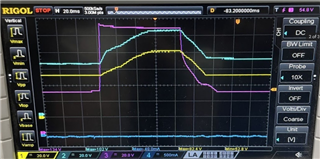
We are using BQ76952 in a 16S BMS. In the event of an Over-current during charge, the AFE turns OFF the charge FETs by command of the microcontroller based on charging current thresholds. After the FETs were open, we observed an increase of voltage on the pack+ pin to 95V, followed by an unintentional rise in AFE CHG pin voltage driving the charge FET gate. This leads to charge FETs operating in linear regions and hence getting damaged.
Signal definition:
- Yellow: Charge FET gate w.r.t Ground(BAT-)
- Light blue: BAT+
- Purple: MATH function where it represents Charge FET gate to source voltage
- Pink: Drain common to CHG and DSG FET w.r.t Ground(BAT-)
- Dark Blue: Current where 1V represents 10A
Here is a snapshot where Charge FETs get damaged after shifting into a linear region
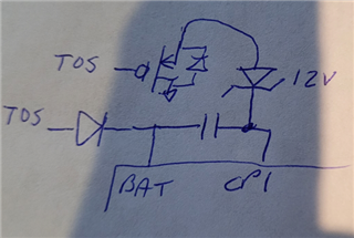
The Mosfet gate circuit followed in the above design is according to TIDA-010208.
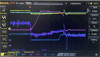
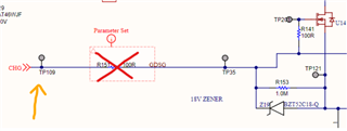
The following test was performed to deduce leakage in voltage from the AFE CHG pin by removing the current limiting resistor and measuring the voltage of the CHG pin.
Here, DSG FET and CHG FET were turned OFF, and the battery voltage was approximately 53V. On a surge of 135V on the PACK+, a voltage induced in the CHG pin and Charge pump was observed internal to AFE. This suspected rise in voltage could be the cause for charge FETs entering the linear region and, hence, the failure.
Signal definition:
- Yellow: CHG pin w.r.t Ground(BAT-)
- Pink: Drain common to CHG and DSG FET w.r.t Ground(BAT-)
- Dark Blue: Current
- Light Blue: CP1 pin w.r.t Ground(BAT-) ( hidden behind yellow signal)