I am designing a flashlight device that utilizes an esp32 to provide pwm signal to dim two separate cree xpe2 leds. These two LEDs are different colors, and practically there isn't a need to have both illuminated at the same time. They both have a forward voltage around 3.1V. I have a couple of questions regarding how to design around the TPS 92201.
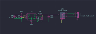
First, I am not sure how to set the output voltage, the data sheet states that output voltage is set with R1 and R2, but there is no R1, R2 in the example schematic. Are these just a resistor divider before the Vin pin?
Second is regarding optimal design around the device to drive the two leds. I currently have two separate 92201 devices, each with a separate pin from esp32 driving their enable pins, and separate pins providing each PWM signal. The leds are on a separate aluminum board for heat dissipation. In their current iteration, I have a 3 pin connector connecting to the LED board, 2 pins for the separate anodes, and a shared pin for the cathode, marked as G in the schematic. Will this shared cathode pin negatively affect my PWM signal feedback?
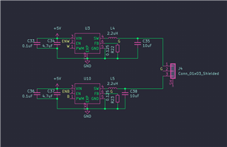
Third, since I have both devices sharing the same PWM clock, but on separate pins, as I don't imagine the need for separate dimming of the individual color LEDs; would it be more efficient to use a single TPS92201 to drive both LEDs and use a SPDT analog switch to change which LED is driven?