This thread has been locked.

If you have a related question, please click the "Ask a related question" button in the top right corner. The newly created question will be automatically linked to this question.

BQ51013B: Combining it with BQ25185

Part Number: BQ51013B
Other Parts Discussed in Thread: BQ25185, BQ24072, BQ51050B

Hi Bill, (I hope this reaches you, since we had already talked about)

Following your suggestion, I am modifying the charger system, using now a BQ51013B and a BQ25185 together, to charge a 1 Cell LiFePO4 Battery.

Here are the key-specs of the batt:

- Nominal Capacity 600mAh At 0,2C CC discharge

Minimal capacity 600mAh

Nominal Voltage 3.2V

Charge voltage 3.65V Max. 3.8V

Standard Charging

0.5C Standard 2.5 hour nominal

1C max. 1.5 hour rapid

Cell internal impedance ≤102Ohm Measured at 1khz after 50% Charge

- Charging temperature 15 – 25°C Maximum 0 - 45°C

-Standart Charge

Charging cell initially with constant current at 0.5C to 3.65V,

then with constant voltage at 3.65V

till charge current is below 0.02C

-----------------------

And here a preliminary circuit:

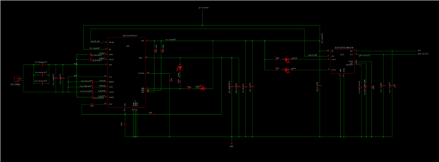
The questions I have are:

- Could you please check, if the circuit is ok like this?

and for the BQ25185:

- I cannot find a way to ILIMt to be 600 mA by having VBATREG 3.65V

The table on P.16 of the data sheet has several values for RILIM/VSET, where ILIM changes between 500 and 1100 mA.

How do I get something in between? And how is VBATREG set?

- The last question refers to the SYS Voltage.
The data sheet says, the voltage is regulated to 4.5V
I only need 2.4V here, since I have an LDO afterwards to regulate the voltages I need in the Load.
Internally pulling the battery voltage high, only to pull it down externally again does not seem to be wise in terms of power dissipation to me.
I cannot find any mention to noise in the data sheet. I suppose, the process is generating some ripple...?

Sorry, too many questions...

Best regards and anticipated thanks for the help,

Gustavo

PS: I changed the circuit image. I had attached an older version.

  • Hi Gustavo

    BQ51013B -- Need to take a closer look at the AD and AD-EN connections.  Typically AD is grounded and AD-EN is floating.

    BQ25185 -- Let me get back to you on this one.

  • Hi Bill,

    thanks for the reply.

    For the AD and AD-EN connections, I followed the design I already had with the BQ51050B and BQ24072, since the pins seem to behave the same.

    The data sheet of the BQ51050B says about this on P32:

    ---------------

    "bq51050B Wireless Power Receiver and Wired Charger

    9.2.2.1 Design Requirements

    The requirements for this solution are identical to the first application so all common components are identical. This solution adds a wired charger and a blocking back-back FET (Q1).

    The addition of a wired charger is simply enabled. The AD pin on the bq5105x is tied to the input of the DC supply. When the bq5105x senses a voltage greater than VAD-Pres on the AD pin, the BAT pin will be disabled (high impedance). Once the BAT pin is disabled, the AD_EN pin will transition and enable Q1. If wireless power is not present, the functionality of AD and AD_EN remains and wired charging can take place."

    -------------

    However is this: "When the bq5105x senses a voltage greater than VAD-Pres on the AD pin, the BAT pin will be disabled (high impedance)", not clear on the data sheet of the BQ51013B. But I hope it will be the same, since on P37:

    9.2.3 Wireless and Direct Charging of a Li-Ion Battery at 800 mA shows in Figure 9-11: BQ51013B Used as a Wireless Power Supply With Adapter Multiplexing for a Linear Charger

    using the same procedure as by the bq51050B Wireless Power Receiver and Wired Charger

    Could you confirm, that OUT will be disabled (high impedance)?

    Best regards,

    Gustavo

  • Hi Gustavo

    Update on the BQ25185 - The schematic looks good, only the typical SYS capacitance should be 10 uF.

  • Hi Gustavo

    BQ51013B -- Need to take a closer look at the AD and AD-EN connections.  Typically AD is grounded and AD-EN is floating.

    Bill J -- Connecting the AD pin to OUT without the switch circuit will be a problem.  When OUT goes o 5V AD will signal for the wireless power to turn off.

  • Hi Bill,

    yes, you are wright, I did not see this "detail".
    By the bq51050B the output is BAT and charges the battery, but since the BQ51013B is not a charger, the combination with the BQ25185 does not seem to be possible in this way. Now I understand.

    I think, we can close this now. I will have to think about another solution (always and only with Ti devices, of course! Blush

    Thanks again and best regards,

    Gustavo