This thread has been locked.

If you have a related question, please click the "Ask a related question" button in the top right corner. The newly created question will be automatically linked to this question.

BQ34Z100-G1: I2C SDA Line pulled low for about 1 sec after chip ack's on 0x55

Part Number: BQ34Z100-G1
Other Parts Discussed in Thread: BQ34Z100, BQ34Z100EVM, BQSTUDIO, EV2400

Hi,

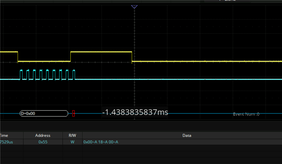
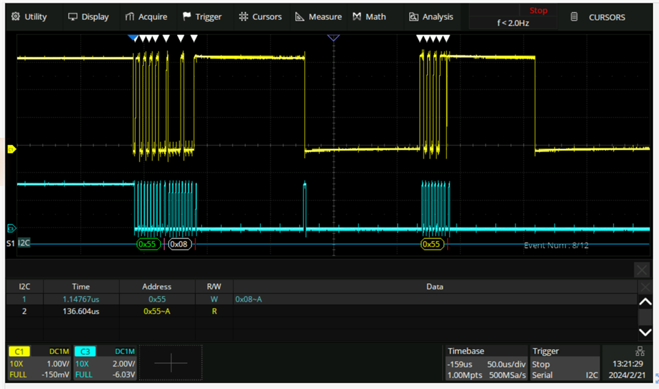
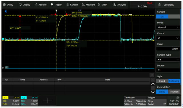
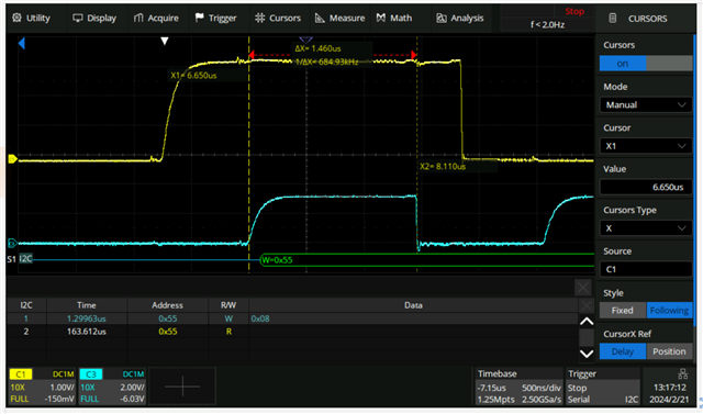
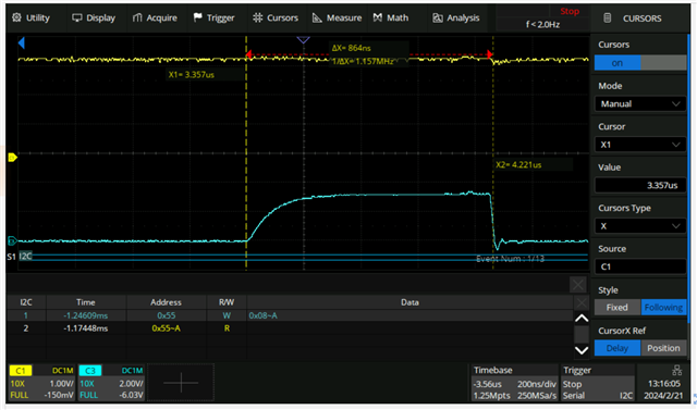
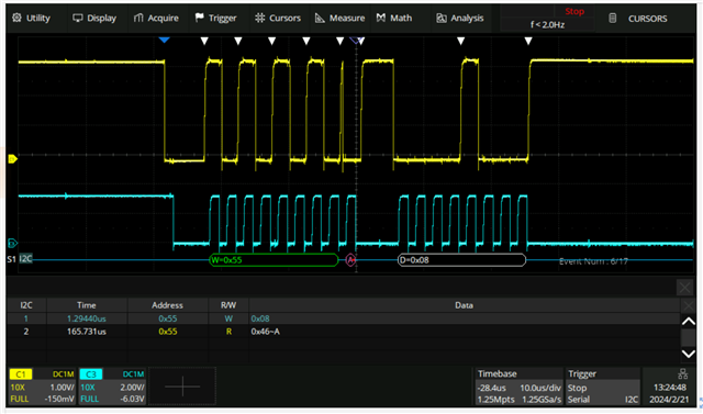
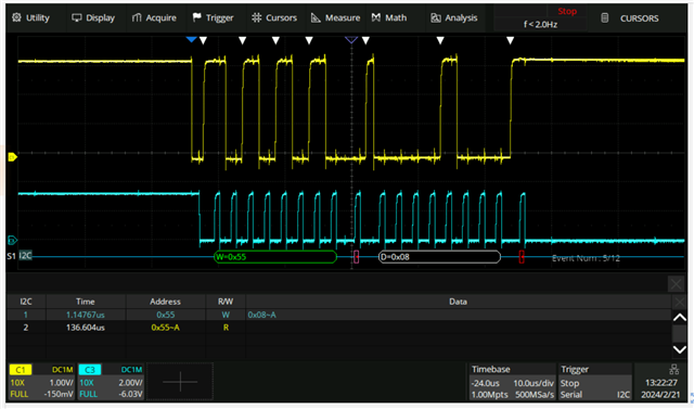
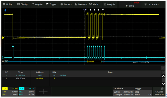
I'm writing a driver for the BQ34Z100 chip, and every time I try to read or write to/from a register on the chip, it pulls low the SDA line on the I2C bus for about 1 second. 

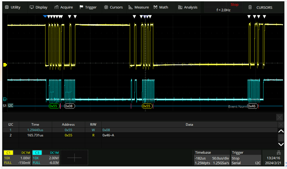
This happens after writing the 0x55 address on the bus, and the chip acknowledges.

After this, e.g. writing 0x08 to read out the voltage, the chip pulls down the SDA line for a long while, usually more than 1 second. 

I have tried with several different registers, i2c frequencies and timings without any luck. We have not re-flashed the chip.

Any ideas on ways forward would be greatly appreciated?
What could make the chip behave this way? 

Below are some screen shots from the oscilloscope. 

An example trying to write to the dataFlashClass register 0x3E. Yellow is data line, blue is clock line.

Chip acknowledges the address 0x55

After the acknowledge of 0x55, trying to write 0x00 to the chip, the chip do not acknowledge and pulls down the data line

  • For some reason, the comments on the pictures disappeared.
    Yellow: SDA
    Blue: SCK
    Image 1: Showing how the chip pulls down the SDA line after acknowleding 0x55, but not acknowleding register 0x3E. 
    Image 2: Detail view of acknowleding 0x55
    Image 3: Detail view of not acknowledging register 0x00 and pulling down the SDA line: 

  • Hi,

    I have a few questions.

    Are you using BQ34z100EVM?

    Are you using EV2400 with BQstudio?

    Regards,

    Evan

  • Hi Evan, thanks for your reply. 

    I am using a BQ34Z100PWR chip.

    No, I am using the chip out of the box communicating with it directly over i2c using a ft2232h chip. 
    I was hoping to do all configuration of the chip over i2c as we are planning on a series production, and flashing every chip with a EV2400 would be time consuming. 

    Best regards,

    Morten Lie

  • Hi Morten,

    Thank you for clarifying.

    Do you have 10K pullups on you I2C lines?

    Do you have 100ms delays in between sending and receiving I2C commands?

    Since you have been unable to communicate with the device before, I have feeling there may be an issue with your setup.

    Do you have schematic of your setup you can share?

    Regards,

    Evan

  • Hello Evan, and thanks again for the feedback.

    Yes, I initially had 4,7K pullups, but tried 10K with no change in behavior. 

    I also have the delay you point out. 

    With the current setup, I am able to communicate with 8-10 other chips on the same pcb over the same i2c bus, so I think the setup is ok. 
    As the BQ34Z100PWR is pulling the the data line low, this halts all communication for that period of time which is unacceptable. 

    I have tried with different i2c frequencies, and tried only communicating with the BQ34Z100PWR chip (silent all other communication on the board). 

    Is the behavior I am facing a fault-mode behavior of the BQ34Z100PWR like if it is not flashed correctly?

    I have tried replacing the current BQ34Z100PWR with a new chip several times, but they all behave the same way.

  • Hi Morten, 

    I have not seen this issue before. You are successfully able to communicate with all other devices except the BQ34z100. 

    Please allow me some time to consolidate my team about your issue.

    In the meantime...

    Can you try reuploading the FW to the gauge. 

    Can you share your .srec file, so I may check that your gauge is not stuck in the wrong state.

    Regards,

    Evan

  • Hi Evan,

    Thank you for consolidating with your team. 

    Like i said, I'm using the chip out of the box, e.g. I have not uploaded any fw to the gauge. My understanding was that the chip comes pre-flashed, is this wrong? Do I need to buy the EV2400 and flash the chip in order to use it? I was planning to do configuration over i2c. 
    Thus, I do not have a .srec file either.

    Best regards,
    Morten 

  • Hi Morten,

    That is what I figured but I thought I should ask. Yes, the devices do come pre flashed and once we fix your I2C issues you will be able to configure it over I2C.

    After consolidating my team, we believe your issue is related to timing, try to match to match the timing diagram from the datasheet.

    BQ34Z100-G1 Wide Range Fuel Gauge with Impedance TrackTm Technology datasheet (Rev. D) (ti.com)

    Here is a o-scope shot I took of the BQ34z100 reading 0x08 from address 0xAA, please try and match the timing.

    SDA on top 

    SCL on bottom

    Regards,

    Evan

  • Hi Evan, thank you for your advice on timing. 

    I have tried connecting an Arduino to the I2C bus on the pcb to figure out if the issue was timing/capacitance in the bus lines. The Arduino is connected to the i2c lines right next to the ftdi, so the length of the bus lines should be roughly the same.

    Using the Arduino, I am indeed able to read data from registers on the chip. But I've not been able to figure out what key differences in the i2c bus setup that enables me to read using the Arduino but not using the ftdi. Both the Arduino and the ftdi are set up with i2c frequency of 400KHz. 
    Below are some o-scope snapshots from both the arduino and the ftdi. 

    Any thoughts and tips for a way forward to solve the issue of reading the BQ34Z100-PWR chip using the Ftdi is greatly appreciated. 


    Read of register 0x08 on the BQ34Z100-PWR (address 0x55). As you see, I'm able to read out data from the register.

    Same read attempt using the ftdi. As you see, the chip does not acknowledge the 0x08 register, and does not acknowledge on address 0x55 on the read command. 

    I have tried to compare the SCL/SDA rise times, but they are both under 300ns. 

    Risetime of SDA on arduino.

    Risetime of SDA on ftdi. 

    I have noticed that the clock width are a bit different, but both are within the timing criteria of minimum 600ns. 

    Clock width arduino

    Clock width ftdi. 

    For some more data, I have provided below close ups from both the arduino and from the ftdi:

    Arduino:

    Ftdi:

  • Hi Morten,

    Unfortunately, this out of my area of expertise. 

    I do know that Arduinos have internal pullups on i2c lines and libraries that handle i2c protocols. Unfortunately, I will not be able to help you with your ardunio or fdti.

    Regards,

    Evan