A related question is a question created from another question. When the related question is created, it will be automatically linked to the original question.
If you have a related question, please click the "Ask a related question" button in the top right corner. The newly created question will be automatically linked to this question.
Part Number: UCC2813-0 Other Parts Discussed in Thread: TL431
Hello,
We are trying to use the UCC2813-0 Switching Controller and we having problems getting it to function properly. Is there any applications engineer that we can work with?
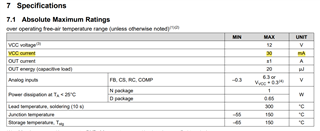
We are using the UCC2813-0 and we are experiencing excess current draw by the part. Specifically we are seeing about 72mA of current flowing into the Vcc pin. In addition to that when our flyback circuit is powered on with a 2A load sometimes our 24V output comes up and sometimes it doesn't.
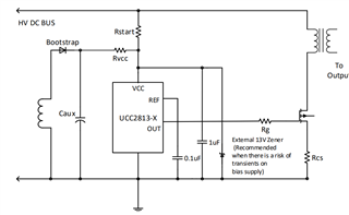
Regarding the Vcc we have this circuit in place with Rstart = 300K; Rvcc = 200R; 11V external zener. Our last attempt caused our Mosfet and current sense resistor to blow up.
I need to check your schematic with your all your component values and input and output specifications to provide a better help. 70mA is way too high (see below). It means that the output pin of the IC is shorted, and this might be due to the main switch that would be damaged.
1. You might not need the external Zener Diode connected at Vcc. According to Section 10 of Datasheet, an internal Shunt Regulator is connected at VCC which helps for startup regulation. An external zener diode is recommended at the end of the section in case there is a need for a HV transient event. An external zener diode consumes more power (1.3W in the case of your zener) when clamped and that reduces the efficiency of your system.
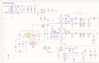
2. I noticed that the TL431 Shunt regulator does not have a bias resistor (R417 in your schematic). Please, place a 1kohm resistor instead to bias the shunt regulator. If not bias correctly, the secondary side will never take control and regulate well as it is unable to provide the correct FB voltage.
3. I do not have enough information to provide feedback about the rest of your components as I do not know your input voltage range Vin_min<Vin<Vin_max, switching frequency fsw, load conditions.
4. If your MOSFET and current sense resistor are damaged, please replace them. Make sure that the IC is not damaged. You can compare the impedance seen at each of the pins with respect to the ground pin and see if both have similar results. You can measure the impedance with a hand multimeter. Or you can also replace it by a new one.
5. If you still having problems, I recommend measuring (VCC-GND), (DRV-GND), (CS-GND) and (COM-GND) with a scope probe. Put the trigger at (VCC-GND) channel, rising UVLO. Make sure the waveforms are label correctly and have good amplitude scale. Time scale can be few ms and also 100s of us depending on fsw.