This thread has been locked.

If you have a related question, please click the "Ask a related question" button in the top right corner. The newly created question will be automatically linked to this question.

BQ25798: BMS034A

Part Number: BQ25798

The problem that I am facing is in the eval board of BQ25798 (BMS03A4) . When the power is delivered to th board the stat led starts blinking. I need to know that what could be the probable reason for the same

  • Hi Poorti,

    What voltage is applied at BQ25798?  If outside the UVLO and OVP window, STAT flashes.  Is your power supply capable of providing the current set by the charger's input current limit?  Did you follow the steps in the user's guide at https://www.ti.com/tool/BQ25798EVM?

    Regards,

    Jeff

  • Hi Jeff,

    I have applied the 5V at the VIN1(J1) CONNECTOR . Once I connected then the stat LED starts blinking but when I connected the load then the blink stops. Also the prog resistor I have choosen is 27kohm . Ifdeally it shouild give 16.8 V at the battery terminals but it fluctuates between 10.2 approx to 13.8 something.  And when I connected the load of 100mA then the voltage level goes down to 2. something and gradually decreases with the same behaviour while applying more load.Please help me out. 

    regards ,

    poorti

  • Hi Jeff, 

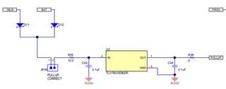
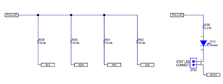
    One more observation from my side is , the probem is occuring when we are connecting the JP30 (PULL UP CONNECTOR) then the Led starts blinking & the Output voltage is fluctuating . When we disconnect the connector then the LED lit off and the voltage at the battery terminals is as required. Also keeping the power source in the same position and then connect the connector then the LED switch on constantly and the current consumption stuck at 100mA without any fluctuations and voltage at battery terminals is also stable. But the power cycle take backs the system to the initial situation i.e blinking LED & fluctuating voltage.

    We found that there must some required configuration between VBUS  & 3V3 bus.

    Kindly help me out.

    Thanks & Regards

    Poorti Varshney

  • Hi Poorti,

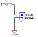
    JP30 connects the output of a 3.3V regulator to pull ups for the LEDs and /CE pin.  If removed, the LEDs can't blink and charge cannot be disabled by removing JP17.  If charge isn't disabled, the pulsing is expected.

    It also pulls up the SCL and SDA but those are likely already pulled up by the communication box.

    Regards,

    Jeff

  • Hey Jeff,

    I have few doubts in the Customised board that we have designed using BQ25798 IC :

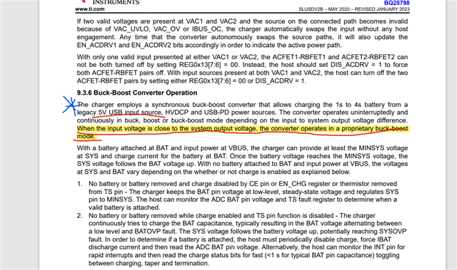
    1) When we are giving input voltage nearby to the VSYS value then only we are getting stable output voltage. It is written in Datasheet also.

    But in Eval Board we were giving input Voltage =5V but in output we were getting multiple output (4.2V, 8.4, 12.6,16.9) Depending upon the prog resistor jumper selection. 

    What could be the reason for the same?

    We have followed the complete design of the eval board only.

    Regards

    Poorti

  • Hi Poorti,

    The EVM board is working correctly. When a valid input voltage source, like 5V USB, is provided to the charger at VBUS, the regulated SYS output voltage is the higher of the minimum system voltage or battery regulation voltage.  The PROG pin resistor sets the number of cells (1,2,3,4), battery regulation voltage and minimum system voltage.  If no battery or simulator is connected at BAT, SYS pulses between MINSYS and slightly higher than BATREG.

    Regards,

    Jeff