This thread has been locked.

If you have a related question, please click the "Ask a related question" button in the top right corner. The newly created question will be automatically linked to this question.

UCC14141-Q1: EMC Issue advise

Part Number: UCC14141-Q1

Hi,

Customer is using UCC14141 for PTC heater project.

There is an issue with EMC testing.

Please give me some advice on how to improve EMC for UCC14141.
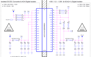
Schematic :

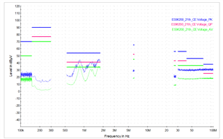
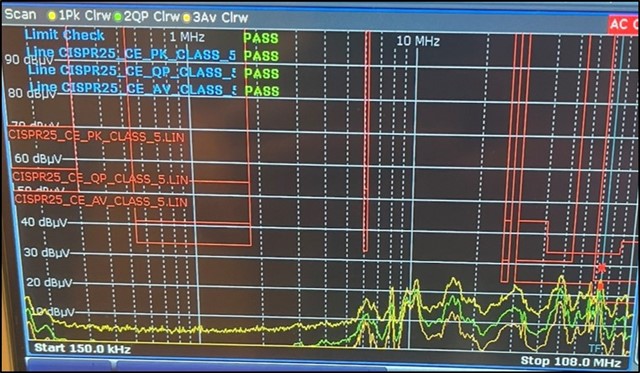
CE(Conducted Emission)

Using UCC14141-Q1  : 45 to 100 MHz band peak value exceeded

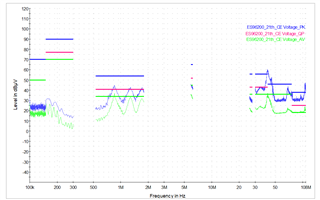
Remove UCC14141-Q1 : 45 to 100 MHz band normal

  • Cho,

    From the scans you are showing, it appears there is likely some low frequency DM filter somewhere in your system? I say this because typically we see some peaks near 150kHz but you're scan does not show any peaks near this frequency range? Also, how far above the noise floor are you failing in the 40MHz<F<100MHz range? An effective CM filter in this range will help and below is the CM+DM EMI filter I have tested and the resulting CISPR 25 CE scan showing Pass at full load (1.5W).

    The chassis connection will need to be connected to either the metallic case that encloses your design or to the conductive table top, close to the LISN.

    Also, the CM and DM inductors should not have any copper beneath the component because this can introduce a potential HF sneak path around the EMI filter. This is not unique to the UCC14141 but common practice for any HF EMI filter mitigation strategy. 

    TIDA-050065C(001)_TI-BOM.PDF

    Regards,

    Steve

  • Hi Steve,

    Thank you for your support.

    The customer is on a business trip, so the answer to the question may be delayed.

    I will share your response quickly.

  • ok - I will close for now but please open up to respond if needed.

    Steve