This thread has been locked.

If you have a related question, please click the "Ask a related question" button in the top right corner. The newly created question will be automatically linked to this question.

LM2592HV: LM2592HVT-3.3/NOPD not regulating to 3.3V under E-load conditions drawing small current (<1A)

Part Number: LM2592HV

Here are the specs of my circuit:

Vin = 9V (works bc 4.75 < Vin < 60)
Desired Vout = 3.3V
Desired Iout = 0 - 2A
Cin = 470uF, 50VDC, Ripple Current = 530mA, low ESR
Cout = 220uF, 50VDC, Ripple Current = 1.15A, ESR = 75 mOhms
L1 = 47uH, Max DC Current = 3.2 A, Max DC Resistance = 100 mOhms, Saturation Current = 3A
L1 = 33uH, Max DC Current = 2A, Max DC Resistance = 140mOhms, Saturation Current = 2A (I also tested it with this inductor value as prompted by datasheet)
D1 = If = 3A, Vrrm = 60 V

I modeled it after the Test Circuit provided in the datasheet (but want Vin = 9V and Vout = 3.3V rather than 15V, 5V as indicated below):
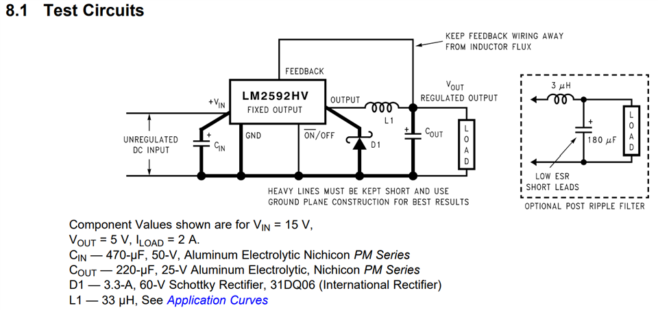
I did not include the Optional Post Ripple Filter. 

The problem I encountered is that when I hooked up an E-load to its output nodes and ran test currents I get these Vout values correspondingly:
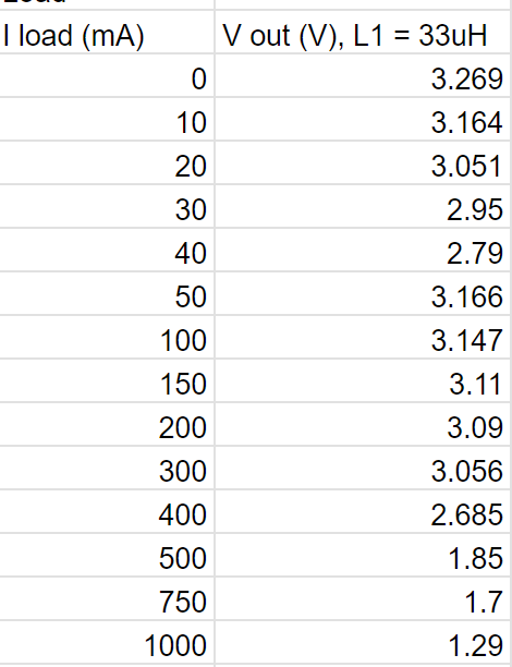

As you can see, the Vout significantly drops as I load increases. Why is this happening? Are my component values wrong?

  • HI Emiliano,

    You may be seeing resistive losses. Can you check the output voltage across the output capacitor and see if it maintains the same.

    If not, I think the issue is due to the output capacitance. Try increasing to see if that fixes the issue. 

    Thanks,

    Richard

  • Understood, what should the output capacitor capacitance, and ESR values be? Datasheet recommends above 100mOhm for ESR but not too high is all I know.

  • Hi Emiliano,

    I would keep with the 100mOhm for the ESR. I would just add a 10uF capacitor in parallel, and then increase in small increments just to see the effect. 

    Additionally, please verify the resistive losses and make sure that the output voltage across the output capacitor is constant. If it is, then you are seeing resistive losses.

    One thing I think is weird is the output voltage regulation. At 30 and 40mA, the output voltage drops significantly, and then rises back up. Can you monitor the SW node and make sure that the part is initially in DCM (figure 16) at lighter loads, and then slowly travels to CCM (figure 15) as load increases? This is just to make sure the design is operating correctly. If it doesn't look like that, there may be an issue with the layout. 

    Thanks,

    Richard