This thread has been locked.

If you have a related question, please click the "Ask a related question" button in the top right corner. The newly created question will be automatically linked to this question.

Looking for a buck converter as a variable constant current source for the operation of approx. 3-6 LEDs.

Other Parts Discussed in Thread: TPS92515-Q1

I am looking for a buck converter as a variable constant current source for the operation of approx. 3-6 LEDs.

Requirements:

  • Current (0.35A ~ 1A) controllable via microcontroller (perhaps via digital potentiometer on the pin for current control?)
  • PWM in 256kHz controllable via microcontroller with possibility to change the duty cycle 128000 times per second
    • or possibility to put a MOSFET at the output for PWM control via microcontroller
  • Lowest possible power dissipation
  • Operation on 18V or 24V direct current
  • Hello Daniel,

    Please give me more information about this application.  

    • What is the Vf of the LED at the min and max LED current setpoint you are planning to use, LED datasheet would be good
    • I don't understand where this PWM frequency of 256 kHz is coming from. Are you sure you don't mean 256 Hz?  Maybe you are talking about the switching frequency of the constant current converter (buck, boost, buck-boost, etc).  Please clarify.
    • What do you mean changing duty cycle 128 kHz?  Duty cycle is usually a percentage of the PWM period?  
    • Are you planning on doing PWM dimming or shunt fet dimming?  
    • Given a max number of LEDs is 6, and lets assume for now your LED Vf at 1A is 3V, then the max output voltage would be 18V, if you want to use a BUCK converter to generate the Constant Current (CC) source then you will want to operate at 24Vin and it won't work at 18Vin.

     I get the feeling you haven't done this before.  PWM frequency of 256kHz is almost unheard of and especially in automotive industry, which is 200-1000 Hz typically).   Here is some training video so that you can learn about the terminology and basics of driving LEDs.

    https://www.ti.com/video/series/led-driver-basics.html 

    If you can get some clarification on your requirements then I can give you guidance on what you should use for your application.  

  • Hi fhoude,

    Thank you very much for your detailed answer.

    We planned to use these LEDshttps://download.luminus.com/datasheets/Luminus_SST-20-WxH_Datasheet.pdf 

    We want to create a lamp that is able to output a kind of wavetable of 128 steps of different duty cycles and the frequency in which the whole wave is put out should be configurable between 1-1000Hz, so for the upper limit 128*1000x duty cycle adjustments per second according to the wavetable.

    Initially we were planning on building the wavetable out of 256 steps, so this is where the 256kHz came from, but we could go down to 128kHz if it makes a difference. 

    Additionally we would like to be able to adjust the current via MCU as well, in the range 0.3-1.0A 

    After watching (https://www.ti.com/video/5780115707001) i would assume shunt FET dimming isn't appropriate.. as of my understanding, if i run 3 LEDs (Vf=3V) at 1A in series at 50% duty cycle then half of each cycle 9W power would be "shorted" via the FET, is that correct? So, we were thinking of using either series FET dimming or main FET dimming if possible.

    As for our approximation of 3-6 LEDs, basically we want to be able to drive multiples of 3 LEDs in series, but it would be nice to use the same/a similar solution later for other projects using up to 6 LEDs in series.

    And yes, you're right, we haven't done this before. It will be for biology experiments in a university and we thought we could try to build it.

    Thank you very much for your support!

  • I think your best bet for a this type of dimming it the TPS92515-Q1 because it uses a hysteretic control and supports very fast transient response.  The regulation accuracy won't be as good but given the need for fast response I think it is your best option.  Shunt FET dimming is an option still, but I would likely try series FET dimming first.  

    I am not sure what you mean be a wavetable.  Can you share more information about that.  128,000 duty cycle adjustments per second?  I am not sure what that means and how  you are getting this.  Generally speaking, pick a specific PWM frequency and then vary the duty cycle to change the % ON time.  For example you have 0.1% resolution then you have a 1000:1 dimming ratio. 

    I would recommend getting an EVM and testing your design prior to doing schematic and layout design.  I can review schematic and layout when you guys are ready.  

    -fhoude

  • Hailee will be helping with follow up questions on this thread.  We don't want to create more threads as it makes it harder to find thread for specific questions.  

  • Hi Hailee,

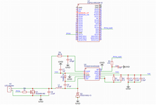
    We have now switched to shunt fet dimming. The current schematic looks like this:

    We plan to use these LEDshttps://download.luminus.com/datasheets/Luminus_SST-20-WxH_Datasheet.pdf 

    Input voltage range: 42V

    Output voltage: approx. 36V (We now use 12 LEDs here)

    Iled: 0.1 to 1.5A (variable via PWM)

    fsw: 128kHz

    Does that look right to you? Do you have any tips for us on what we should do differently?

    Thank you for your support!

  • Hi Daniel,

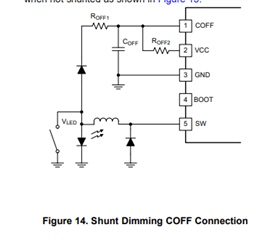
    If you'd like to use a shunt FET dimming, please refer to the below picture for COFF connection and 8.3.4 OFF-Timer, Shunt FET Dimming or Shunted Output Condition in the datasheet.

    I think your schematic follow the EVM design, what are your PWM_IADJ signal and PWM signal? I just want to check your current range and shunt PWM duty cycle. and you can use this tool to calculate the spec that you design - like current ripple, fsw -   SLUC613 Calculation tool | TI.com.  

    BR,

    Hailee.

  • Hey Hailee,

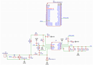
    Thank you very much for your support. We have now adapted the schematic as follows:

    We are not sure how to calculate R OFF1 and R OFF2 and are also not quite able to cope with the Excel table. The ESP32 produces a 128kHz 8bit signal for PWM_IADJ and PWM. Can you tell us which resistor values are best suited and whether the rest of the circuit is also ideal for our project in your eyes?

    Thank you so much!
    Daniel

  • Hi Daniel,

    The parameters depend on your design requirement, like inductor current ripple, input voltage range, output voltage, Viadj....

    You can directly input these requirements in the calculation tool, and post it in this thread, I can help you review it.  

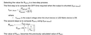
    These equations can be used to calculate the Roff2, and the value of ROFF1 becomes the previously calculated value of ROFF. 

    General speaking, if you follow our EVM design, I think it can work, but please ensure your design specs.

    Thanks! Hailee.

  • Hi Hailee,

    unfortunately we are not able to work with the Excel spreadsheet. We don't know what to enter in too many places. However, we would like to understand the calculator so that we can use it for future calculations. Can you help us with the following questions?


    Input Characteristics

    Vin_min, Vin_nom, Vin_max: We use the MeanWell HLG-600H-42A power supply unit. Datasheet: https://www.meanwell-web.com/content/files/pdfs/productPdfs/MW/HLG-600H/HLG-600H-spec.pdf This has 42V. I assume that Vin_nom is therefore 42. Is that correct? What are the resulting values for Vin_min and Vin_max?


    Output Current Ripple

    LED rD: We don't know how to find out the value for LED rD. We can't find anything about this in the LED data sheet: https://download.luminus.com/datasheets/Luminus_SST-20-WxH_Datasheet.pdf

    ΔILED-pk-pk: We are also not sure what we should enter for ΔILED-pk-pk. Is 0.01A generally a sensible value or should it be adjusted?


    Output Characteristics

    Vout: Does Vout correspond to the sum of all forward voltages of the LEDs in series? We use 12 LEDs in series, each with a maximum forward voltage of 3.1V (see page 7 of the data sheet). Would Vout then be 37.2V?

    Iout: We want to operate the LEDs with 0.1A to 1.5A and be able to set the value variably. We have therefore set Iout to 1.5A.

    Ilpk-pk %: Unfortunately, we don't know what to do with the Ilpk-pk %. Can you tell us more about this?

    fsw: We want to change the Duty Cycle with 128kHz. However, as the specification fsw appears to be the internal frequency of the chip, it could also remain at 500,000. Correct?

    n estimate: Unfortunately, we do not know what value is being queried here. Can you tell us more about this?

    ILED-SoftStart Time: Does this only refer to the initial switch-on or to each individual pulse?


    Undervoltage Lock-Out

    VUV-RISE, VUVLO-HYST: What would be sensible values here based on our 36V Vout?


    R7 Value for shunted condition

    Vout Shunted: Unfortunately, we do not know what value is being queried here. Can you tell us more about this?


    Thank you so much!

    Daniel

  • Hi Daniel,

    The detailed calculation is shown in the datasheet from page 21 of 9 Application and Implementation. I think it is a very useful reference to see the calculation process and a design example of 9.2.2 Design requirements --> just follow these steps, it is clear to see the design considerations. and in our calculation tool, there is a sub- table of the <spreadsheet guide>, please look at it first.

    Vin_min, Vin_nom, Vin_max: It depends on your input character, if there is constant voltage, and no voltage fluctuations, you can use 42V directly.

    rD: Calculate the dynamic resistance as the slope of the LED exponential DC characteristic at the nominal operating point. For example: one of your LEDs - rd = 0.42/(2.0-0.35) = 0.165 ohm, rd of total 12LEDs = 1.98ohm.

    ΔILED-pk-pk: typical value is 10% of Iled. you can change it according to your design.

    Vout: Yes, your understanding is correct. But from your LED datasheet, the maximum forward voltage at 350mA is 3.1V, if the forward current is higher than 350mA, Vf is supposed to be different.

    fsw: the switching frequency is changeable; you can set it accordingly; Iout: Yes, the max If of your application should be 1.5A, please use this value in your design.

    n estimate: it means the estimated efficiency, generally 90% or around; Undervoltage Lock-Out: it is used for input voltage threshold value.

    R7 Value for shunted condition: when you complete the above process, you can get the Roff - R4 in the calculation tool, just follow equations(8),(9) by adding Ilpk-pk, Vshunt, and Coff to get the R7.

    BR,

    Hailee.

  • Hi Hailee,

    Thank you for your quick reply as always.

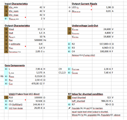
    We have now entered the values as follows:

    We have noticed that the change in "n estimate" from 1.0 to 0.9 makes a huge difference in Roff (changes from 56,7E-6 to 7,9E-6) and R7 (changes from 68E+3 to 9E+3). Is that correct?

    Our Vout is 37,2V. What would be sensible values for VUV-RISE, VUVLO-HYST and VUV-FALL?

    We also do not know how to determine the correct value for Vout Shunted.

    Does the calculation look right to you in general?

    Kind regards
    Daniel

  • Hi Daniel,

    Generally, n can be 0.90 or so, it is affected by many factors; Iled-pk-pk is the LED current ripple, Il-pk-pk is the inductor current ripple - depends on the desired fsw, the L size, efficiency... also it is a balance between these factors. In the application design of the datasheet, Iled-pk-pk is 10%, and Il-pk-pk is 45%. you can change it according to your application.

    For UVLO function, it is a protection for input voltage, if your Vin is very fast, this function may be not necessary, but if your Vin is not fast, it needs to be considered, these values should be above the LED minimum voltage you would want to set it at ideally, and below the min input voltage, then the hysteresis is sort of dependent upon the application, but you can still set it in this range.

    Vshunt is the output voltage when the shunt device or LED Matrix device is ON. For example, Rdson of shunt FET is 0.05ohm, ILED=1.5A, then, Vshunt = 0.05 x 1.5 = 0.075V.  

    we have some videos can help you understand our driver better - LED driver basics | TI.com 

    BR,

    Hailee.

  • Hi Daniel,

    I will close this thread, if you have any other question, please post a new one or continue in this discussion.

    Thanks!

    BR,

    Hailee.