This thread has been locked.

If you have a related question, please click the "Ask a related question" button in the top right corner. The newly created question will be automatically linked to this question.

TPS62113: noise issue from SW pin

Part Number: TPS62113
Other Parts Discussed in Thread: TPS62902

Hello,

I have an issue with my application that is noise sensitive.
I have a receiver with high gain working in the bandwidth of 1MHz center frequency and 300 kHz span.

We use the TPS62113 sync pin with 1250 KHz to force the switching frequency to be outside our bandwidth.

It work well but I notice that we get radiated noise from SW pin at other frequency wish I think that may come from the PWM of the regulator.
We have tried different sync frequency and we always have peaks in our bandwidth.
Is there a way to determine where theses frequencies will be and force them outside of ou bandwidth ?

Will finding a regulator reference that have much higher switching frequency will guaranty no radiation in our bandwidth ?

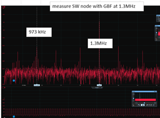
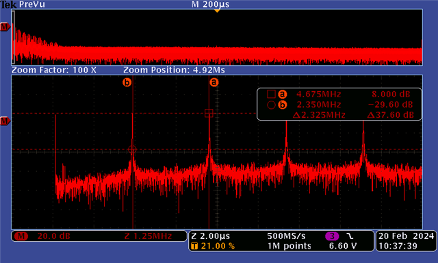
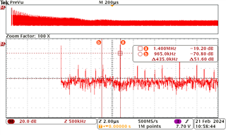
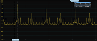
Bellow is the spectrum of the SW pin. 1,25MHz is the switching frequency and 970kHz peak come from the PWM.
I notice that the 970 kHz frequency vary depending of Vin and Vout of the regulator so that why I suspect that this is the PWM.
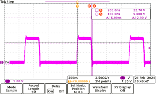
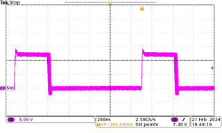
Temporal measurement of SW pin with persistent mode (used sync frequency is different from the FFT above):

Regards.

  • I was thinking about choosing an alternative part having higher frequency available to force the noise generated by the SW pin being outside of our bandwidth.

    A pin-to-pin compatible chip will be the best solution, but I can’t find one. A smaller footprint solution could allow us to move the inductor where it will be isolated.

    We still need low Iq, light load mode , low battery detection.

  • Hello,

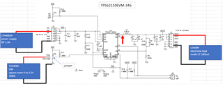
    I have done some more measurements on the TPS62110EVM-346 evaluation board and I was able to reproduce the same behavior as the TPS62113 on our design.

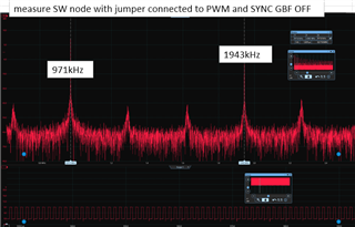
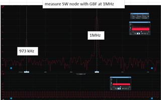
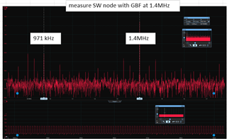
    Measuring the SW node with different SYNC clock frequency or pulling SYNC pin to '1' I found that the 971 kHz peak frequency is always present.

    The noise that cause issue on our receiver seems to come from the internal oscillator or something in the component that I cannot change using the SYNC pin.

    Regards.

  • Hi ErwanLG,

    My team Shuai will reply you after the holiday (after 2/17). Appreciate your understanding.

  • Hi ErwanLG!

    Do you mean your receiver get 970KHz noise by radiate ? You can take a look at TPS62902, it is newest low Iq device, has smaller size and can be set into 2.5MHz.

    BR

    Shuai

  • Hello,

    Yes I get 970 kHz by radiate and I am looking for a solution to shield the inductor. The problem is that I don't expect the 970 kHz to be present on the output of the controller as I use the SYNC pin to force the switching frequency to 1000 kHz 1300 kHz or 1400kHz as shown above.

    Do you know if this is a normal behavior of the controller ? I don't understand where it come from as I have found the 970 kHz on the eval board measuring SW pin with an oscilloscope.

    Thank you for the part number, I will consider to use it if we update our layout. Can I have confirmation that if I set the frequency to 2,5MHz there will be no frequency between 850 and 1250 kHz as the TPS62113 seems to do ?

    Regards.

  • Hi

    I can do bench test for TPS62902 to see whether there is obvious <1.25MHz frequency.

    Shuai

  • Hi

    Below is FFT of TPS62902, 12VIN-1.8VOUT 100mA. It doesn't show frequency <1.25Mhz and >0.85MHz

  • Hello,

    As I can't update my layout for now, I still need to know why I have the 970 kHz on the TPS62113 SW pin while I am syncing it to another frequency.

    Regards.

  • Hi 

    It looks like TPS62113 has relatively large jitter, this may be the reason case lower-than switching frequency component.

    Shuai

  • Hello,

    What are the jitter for you? For me it is the variation of the clock frequency. As i can see is in temporal there is only the PWM that vary and the clock seems stable.

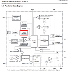
    If I look at the TPS62113 internal block diagram and my measurement in PWM mode, it seems that the 970kHz come from the internal oscillator.

    I don't understand how 970kHz can be present on the SW pin as the MOSFET should be driven by the SYNC frequency and not the internal oscillator anymore.

    Also I still have the 970kHz at whatever SYNC frequency I use.

    Regards

  • Hi ErwanLG!

    I think your issue is related to SYCN function of this device. I have done some test, I found when I use SYNC function to let switching frequency sync with the external frequency. The duty cycle will has relatively large variation compare with its default frequency.

    Here is some results.

    1. Use external clock SYNC as 1.4MHz. There is a 960KHz frequency in FFT.

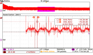
    2. Use external clock SYNC as 0.82MHz. There is a 656KHz frequency in FFT, its percentage is large than that of 960kHz in above image. Let us go back to see its duty variation, it is also large than above 1.4MHz image. So I think large duty cycle variation can cause lower-than main frequency harmonic.

    The duty cycle variation is mainly related to the noise in the system, it is difficult to filter out. So I suggest you to choose higher switching frequency device such as 2MHZ or 2.5MHz.

    BR

    Shuai