This thread has been locked.

If you have a related question, please click the "Ask a related question" button in the top right corner. The newly created question will be automatically linked to this question.

TLV1117LV: TLV1117LV12 Output Unstable Problem

Part Number: TLV1117LV
Other Parts Discussed in Thread: TLV1117

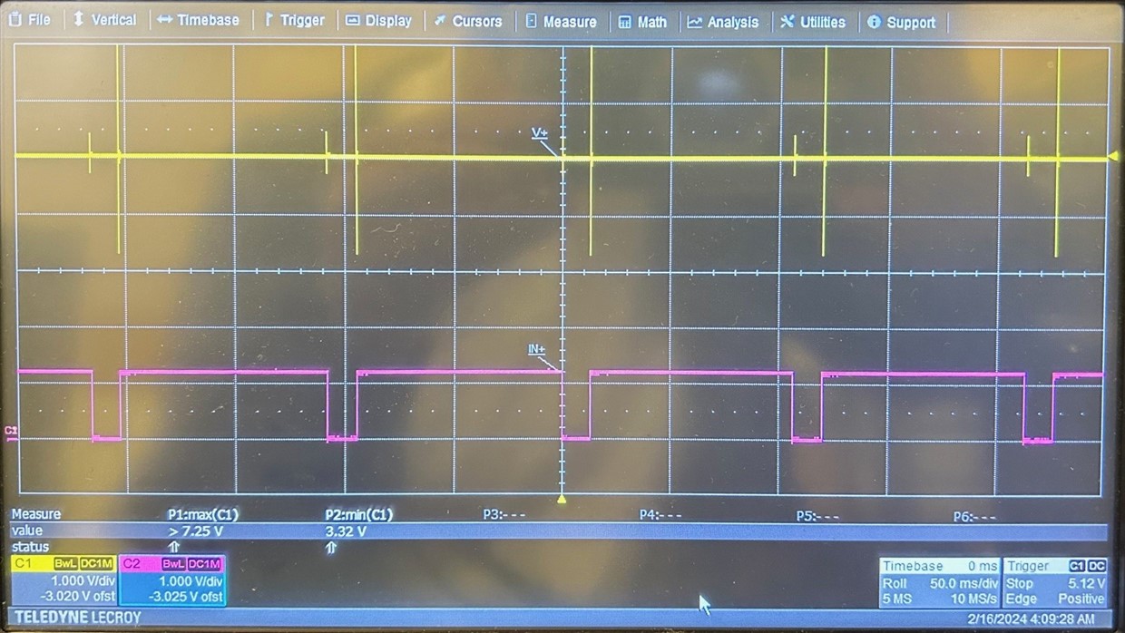
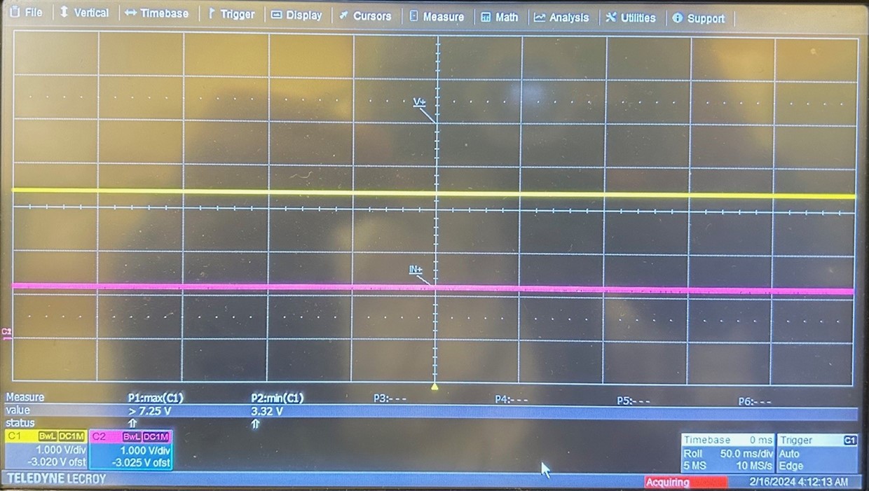
I use TLV1117LV12 in our system MCU power. The input voltage is 5V and output load is around 0.3A. We find when we increase load up to 0.4A, then the output voltage become unstable. Please refer to below waveform. Even I increase the output capacitance from 1uF to 4.7uF that the output still unstable.

I find a interesting things that I decrease input voltage from 5V to 3.3V, then the output can be stable. But it still fail when I increase the load from 0.4A to 0.5A. 

May I know what is the LV12 output max current? is 0.8A or not?

What is the reason cause the output unstable?

Thanks 

BR, Gary

CH1: Input voltage, CH2: Output voltage, Unstable waveform at 0.4A
CH1: Input voltage, CH2: Output voltage, Stable waveform at 0.3A
  • Hey Gary,

    Can you send us your schematic?

    What is happening on the input? the LDO looks like it is turning on and off rather than being unstable. 

    How is your waveform impacted if you increase your input capacitance?

    Best,

    Juliette

  • Hi Juliette,

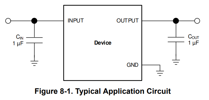
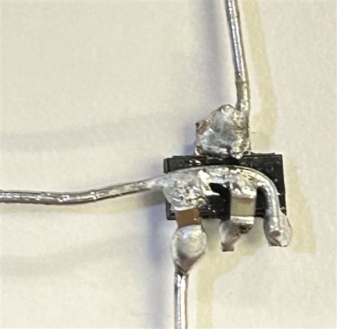
    The schematic is following datasheet. I connect the input/output capacitor around the TLV1117 as like below picture.

    The input voltage comes from the DC source. I don't think that the problem comes from the input.

    I had increase the input cap from 1uF to 4.7uF that the 0.4A can be stable. When we increase the load up to 0.5A, then the output become unstable. 

    May be you can double check in your side? The datasheet shows the 1.8V output can be load 500mA based on input/output at 1uF. May I know what is difference for the 1.2V output.

    BR,

    Gary

  • Hi Gary,

    Your LDO is going into thermal shutdown.  The thermal impedance listed in the datasheet is characterized in accordance with the JEDEC standard, and is a strong function of the board layout. In this case you don't have a PCB so the device can only radiate heat away (as opposed to radiate and conduct through the PCB).  You may wish to try this test on an evaluation module to better predict actual performance when mounted onto a PCB:

    https://www.ti.com/tool/TLV1117LV33EVM-714

    When you decreased Vin, you reduced the power dissipation across the device and cooled the junction temperature as a result.  This prevents the LDO from entering thermal shutdown.

    Thanks,

    Stephen

  • Hi Stephen,

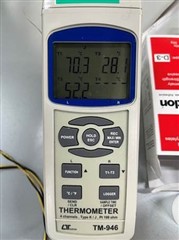
    The customer help to measure the case temperature. It's around 70.37C. The TLV1117 is on their system PCB board.

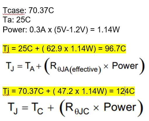
    May I learn from you how to calculate the junction temperature?

    There are two equation, but the result is very difference. May I know which one is correct? 

    BR,

    Gary

  • Hi Gary,

    The power across the device = Pd = (Vin - Vout) * Iout = (5V - 1.2V) * 0.4A = 1.52W when the device is failing and 1.14W when it is working.  Thermal shutdown is typically 165C and assuming your ambient air temperature is 25C, the thermal resistance is approximately 90-100 C/W.

    The thermal impedance Tja listed in the datasheet is per the JEDEC standard. This standard attaches the GND pin to ground copper in the PCB to dissipate heat, which does not exist in your test setup.  When the device is not mounted onto a PCB, the thermal resistance is the summation of the junction to case and the case to ambient.  The case to ambient thermal resistance is not listed in the datasheet and we do not have this characterized for this device.  For further details please see this article:

    https://www.ti.com/lit/an/spra953c/spra953c.pdf?ts=1708100164416

    Thermal time constants are usually measured in miliseconds but temperature measurement equipment such as this handheld device cannot sample that fast.  It looks like this handheld device samples on the order of 1 second or slower, which is far too slow to capture the dynamic rise and fall of the junction temperature.  Based on your oscilloscope plots, the junction temperature cools 20C in approximately 20ms (thermal shutdown occurs at 165C and the device turns back on at 145C).  If we approximate the rise and fall of temperature to be linear (which is usually a good approximation at such short intervals) then you need sample rates much faster than 150ms to accurately measure the dynamic temperature of the junction.

    Thanks,

    Stephen