Other Parts Discussed in Thread: UCC28951, UCC28950
Hi to all,
I'm developing a PSFB application with UCC28951. It is a DC powered converter with syncronous rectifiers, nominal output current is 60 A. The transformer is in center tapped configuration and the converter frequency is 100 KHz.
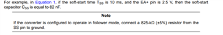
If I use the UCC28951 in master mode, all is functioning, except a bit of duty cycle instabilty over 60 A (due to sub-harmonic oscillations). But if in the same board I change the configuration to slave mode, with Rt resistor to GND, 825 K to SS pin, and with a 200 KHz 50% SYNC reference, I'm not able to get more than 20 A.
Here some oscillographs:
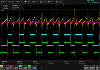
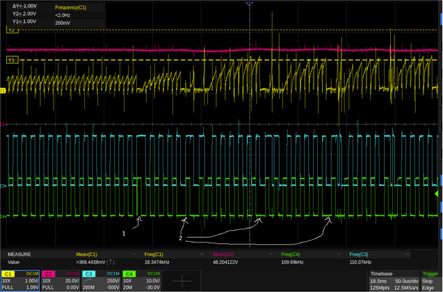
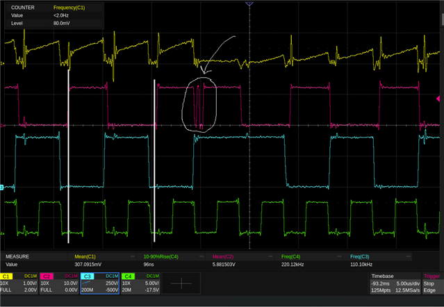
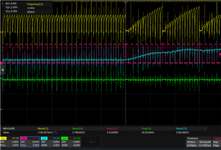
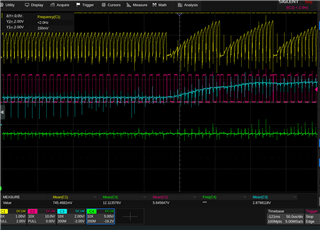
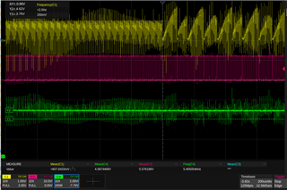
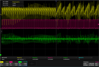
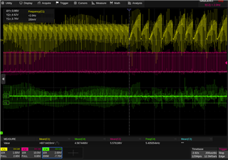
Here is with an output current of 57A, all is stable. RSUM is 22K and the UCC28951 is in master mode.
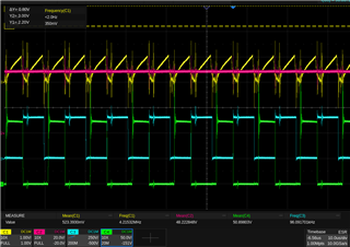
C1 (yellow) is the CS pin. C2 (purple) is Vout. C3 (light blue) is Drain of QD. C4 (green) is the Drain of QE.
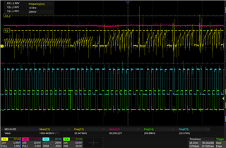
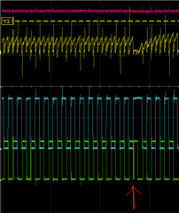
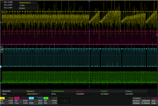
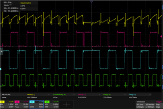
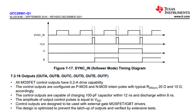
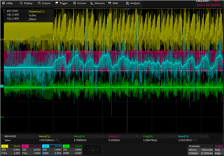
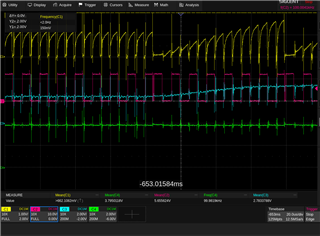
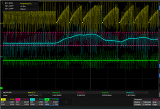
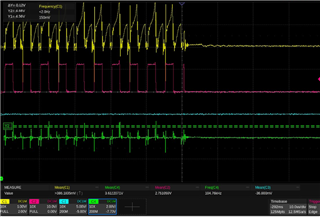
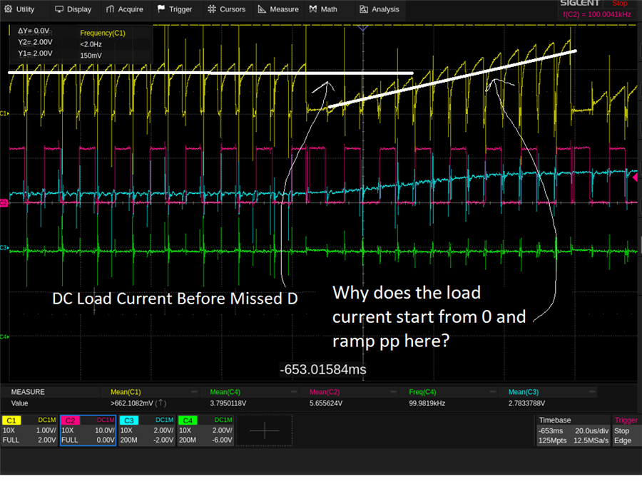
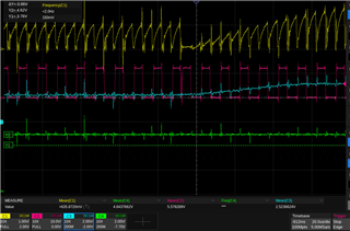
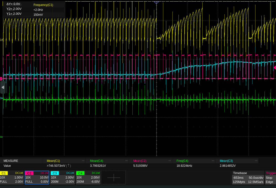
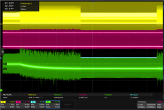
Here is the transition from 19 to 20 A output in slave mode with external SYNC signal:
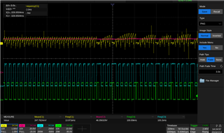
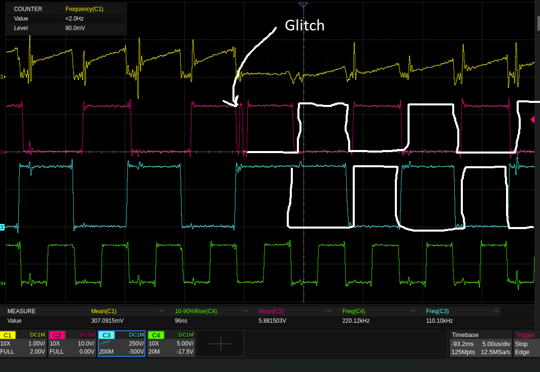
C1 (yellow) is the CS pin. C2 (purple) is Vout. C3 (light blue) is Drain of QD. C4 is OUTA from UCC28951. As you seen it seems that the controller stop and then restart, I don't understand why.
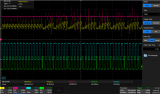
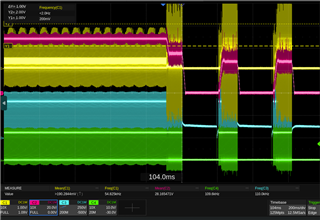
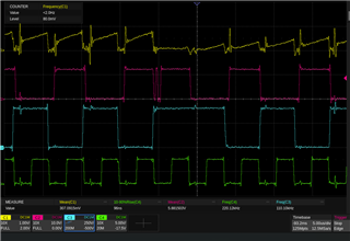
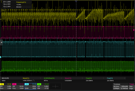
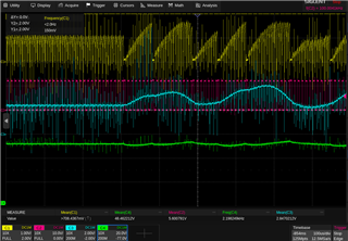
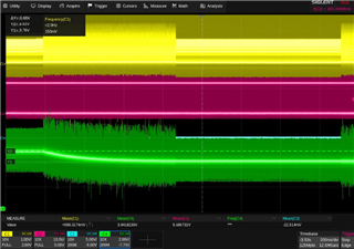
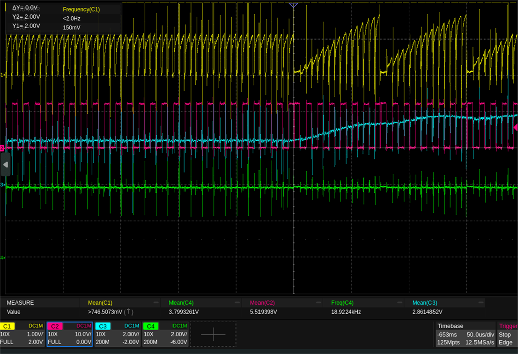
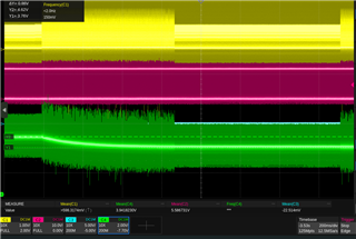
Here is showed the SS/EN pin (C2, purple) during this transition. There are no signs of discharge. The SYNC signal is generated from a microcontroller and is always stable.
Any idea to explain this behaviour?
Thank you.