This thread has been locked.

If you have a related question, please click the "Ask a related question" button in the top right corner. The newly created question will be automatically linked to this question.

LM5116: 12V vs 5V Circuit Problems

Part Number: LM5116

Hello, 

I have a design that is using the LM5116 for both 5V and 12V buck converters. I have seen some failures with the 12V circuit but not on the 5V circuit when there is sparking (e.g. after connecting to a battery directly). I decided to look at the oscilloscope of the low side mosfet VDS and see that the voltage is crazy sometimes upon startup for a brief period of time. Thereafter, it does not have these spikes. The 5V circuits never seem to have this behavior. Do you have any ideas about what differences in the schematic may be causing this abnormal activity on 12V vs 5V? 

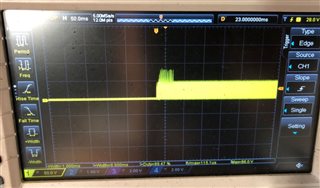
This first scope shot is zoomed out and showing the nasty peaks that exist for about 50 ms upon startup. Thereafter it goes away. 

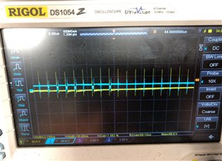
This second scope shot is zoomed in and looking at the VDS signal of the low side (yellow) and the VDS signal of the high side (blue) during that startup sequence.

Please let me know if there is any advice about component selection on 12V vs 5V that could be causing this. For the 12V circuit, I had referenced AN-1713 for the circuit. 

 Power_Board.pdf

  • Hello Justin 

    I think you are seeing the forced LO turn-on which can happen during soft-start. 

    Please try lower gate charge & lower parasitic capacitance MOSFETs and check if any improvement. 

    -EL  

  • Hi Eric,

    Unfortunately changing the MOSFETs isn't really an option here. Do you know if there's any other way I can try and reduce this? Just to note again, this does not happen on the 5V circuit (also shown in the schematic). Any ideas why this is happening on the 12V circuit but not the 5V? 

    Thanks. 

  • Hello Justin 

    That's is just an experimenet. If we get the confirmation that the forced LO turn-on is causing the issue, we can think about other options. 

    I don't have answer now. 

  • I don't think it's a quick thing that I can do for this experiment. However, I'm wondering if I should experiment with other things that are easier to do, such as increasing or decreasing the soft start capacitor, changing switching frequency, adding a snubber across the low side MOSFET, or increasing the resistance of the current sense resistor. Do you think any or all of those could help reduce this effect?

  • Hello Justin 

    Then, please capture  V(SW-GND), V(LO-GND), V(HO-SW) and Inductor current waveforms together at the SW node falling and the rising edges.

    Please zoom in enough. I think ~ 50ns/div scale is good

    -EL  

  • I am closing this thread since I have not heard from you for sometime.
    If you are still trying to resolve the issue, please feel free to open a new thread. Thanks
    - EL