This thread has been locked.

If you have a related question, please click the "Ask a related question" button in the top right corner. The newly created question will be automatically linked to this question.

UC3875: Fast linear change of oscillator frequency, then double-pulse

Part Number: UC3875
Other Parts Discussed in Thread: UCC28951

I have odd behavior of a UC3875DWF.  When a Power FET blows, it occurs after a number of weird "frequency drift with double-pulse" occurrences.  The same IC on the same board will work most of the time.  This 10V, 10A modulated AC supply drives the filament of a power tube.  When the filament is cold it is almost a dead short.  The supply runs until it hits a hardware current limit that pulls the CS+ pin to VREF, initiating another soft-start.  This continues until the filament warms up.  The worst case occurs at high line, when the duty cycle (phase shift) doesn't need to change much to generate an over-current condition.

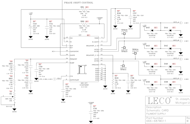
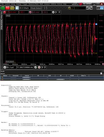
I've attached a screen capture of the schematic and transformer secondary current (because it's easy to measure without affecting the card) of two different start-ups.  The purple trace in "m4" is a normal startup that had no issues.  The red trace in "4" failed a Power FET.  The red trace matches the purple one with an identical constant operating frequency... until it doesn't, as shown here.  The first five cycles have the correct operating frequency.  The frequency then seems to increase linearly until it is 180° out of phase from what is expected after five more cycles.  After five more cycles we are nearly 360° from expected and then the oscillator seems to 'skip back' to normal and a double-pulse results.  As a result, the capacitively coupled transformer primary is offset and while on its way to recovery an over-current occurs.  About 50ms later the soft-start phases on and the situation repeats... until a FET blows.

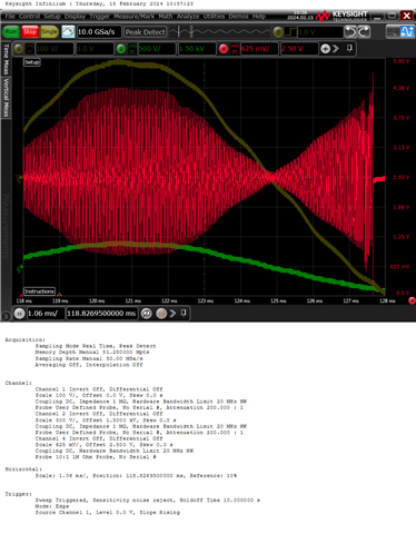
The third image shows how the phase shift controller is modulating the rectified 60Hz AC Mains... until the glitch near the end and the subsequent over current trip.

Looking at the datasheet, I see nothing that would affect the oscillator frequency.  A schematic is attached and what you don't see is a discrete scaling and integrator stage that drives the IC error amp as a buffer.

What could be happening?  What should I look at next?

  • Hello,

    Your inquiry has bee received and is under review.

    Regards,

  • Hello,

    If you want to initiate a soft start, I think you might be better off shorting the SS pin to ground rather than pulling up the CS pin to Vref.

    I only see a schematic of the controller do you have a full schematic that you could share?

    When it comes to trouble shooing this I would study the error amplifier output, CS and input voltage of the transformer and the output.  I would trigger on the CS on the over current trip point so you can get a snap shot of what happens before the failure.

    Regards,

  • I can confirm that the CS+ pullup is effective in pulling the Softstart pin to near zero.  This also 'resets' our control feeding the EA+ pin.

    I can't share more schematics, but I can tell you what you don't see is OUT_A and B, driving a 1:1:1 gate drive transformer primary [ush-pull, and the same for OUT_C and D.  The secondaries drive gate resistors and FETs in a full bridge which drive a step-down transformer primary in series with a cap.  The current monitor signal looks at the secondary.  This arrangement performs as expected WHEN the oscillator frequency remains constant.

    It would be nice to have more signals, but I'm limited to two scope channels in my setup (two others are used for line voltage monitoring, triggering, and monitoring).  I was planning to monitor the VREF signal as that appears to be used in the IC oscillator (as soon as I have this board repaired).

    I need to understand how the oscillator could change frequency, which is obviously happening.  The double-pulse also seems quite obvious, but I really need to look at the OUT_x signals to confirm this.  I'll need to get my hands on another scope and a couple more diff-amp probes to act as the trigger and monitor, so I have more channels for monitoring.  And then I need to wait until this anomaly occurs to get more waveforms (and then I need to repair the board again).

    And regarding "what happens before the failure", you can see it in the scope captures.  If you'd like to see more I can share the Keysight h5 file or more screen captures.

    Any more thoughts would be helpful...

  • Hello,

    The frequency of the controller output should not be changing.  If it looks like the C and D legs frequency cuts in half, this is because controller has phase shifted these legs to demand 0 duty cycle.  That might be why it looks like the frequency is changing but it is not.

    The following link will bring you to a customer describing a similar issue with the UCC28951 phase shifted full bridge controller.  Please take a look at the thread it may help you understand what is going.

    https://e2e.ti.com/support/power-management-group/power-management/f/power-management-forum/1072207/ucc28951-q1-erratic-c-d-drive-outputs-even-with-both-voltage-and-current-well-below-setpoint

    When trouble shooting a phase shifted full bridge it will be a lot easier process if you have a 4 channel scope to evaluated the design. 

    Regards,

  • Mike,

    There was a lot of info in the post you referenced, but I can say that I have neither the CS+ nor the adaptive delay issues.  The current sense waveform is monitored by a comparator and if either the positive or negative current exceeds their threshold the comparator pulls the CS+ pin up to VREF.

    Sorry, I wasn't aware you likely can't discern the various waveforms in my screen shots.  Here's a black/grey/white version of the screenshot of interest, showing the frequency drift between 'normal' operation and the 'occasional failure'.

         [well, I can't insert a picture here, with copy/paste or insert/image/file]

    So, if you go back to the 2nd screenshot I posted... the horizontal yellow lines at ±2.3 divisions is approximately the comparator window.  The spikes on the waveform are likely from the probe ground lead, but the little bit of filtering at the comparator may allow it to ignore these.  "m4" is a purple trace that is in scope memory showing the 'normal' behavior with a nice, steady two cycles per division.  "4" is the 'drift' behavior as a red trace aligned on the scope with about the same amplitude and 'phase' at the start.  Five cycles of "4" run at the same frequency as "m4", but then the frequency increases until, ten cycles later, the red trace has shifted 360° from where it should be, based on the "m4" waveform.  At this point there is a double-positive-pulse of "4" followed by three more pulses that seem to slow down until they are again aligned with "m4".

    This anomaly trips the comparator which initiates a soft=start and, about 55ms later, the chip fires up, repeats this behavior, and eventually a FET fails.

    There is a worst case load of 6.5mA on VREF... I can't imagine that has anything to do with this...

  • Hello,

    Your inquiry has been received and I will get back to you shortly.

    Regards,

  • Hello,

    In your waveform of transformer current, I don't really see the frequency changing between the grey and red.  However, I do see the phase shift you were talking about.   If these currents were taken off a split secondary winding they should always be 180 degrees out of phase.  Also in a normal phase shifted full bride converter the currents do not look like this.


    The phase shifted full bridge is generally designed for DC to DC applications.  In your design the currents seem to follow a sine wave which is not standard.  Generally you would design a phase shifted full bridge for a 3 to 1 input range.  5 to 1 at most.  So your current waveforms may be in regards to the way that you are using the controller in your design.

    The A and B outputs will be synchronized to a master clock and C and D outputs are phase shifted to obtain the duty cycle required by the design.

    You may be getting this behavior due to how these outputs are driving the H Bridge across your transformer producing the phase shift.

    Regards,   


  • This IS NOT your typical DC-DC converter.  This application modulates the AC Mains.

    These waveforms ARE NOT different phases of a transformer.  They are from two different runs of the same board, in the same setup, just at different times.  The 'grey run' operated as expected, continuously.  The 'red run' did not, with the double-pulses occurring every second or third AC Mains cycle until failure of a FET.

    You can see that the frequency of the 'red run' did change as described, simply look at the zero crossings.  The frequency of the 'grey run' did not and everything behaved as it should.

    The reason I put the two different runs on the same screen was because it seemed the 'double-pulse' of the 'red run' (14 cycles in) would coincide with the phase 'realigning with where it should have been', as shown in the 'grey run'.  It turns out this was correct.

    I apologize for not having more information to share... we have two out of our three nice scopes out for calibration.  When I get more channels to work with I will add the OUT_A-D signals...

  • Hello,

    Your inquiry is under review.

    Regards,

  • Hello,

    Thanks for letting me know. 

    Regards