This thread has been locked.

If you have a related question, please click the "Ask a related question" button in the top right corner. The newly created question will be automatically linked to this question.

TPS2121: TPS2121 IC failure

Part Number: TPS2121
Other Parts Discussed in Thread: TINA-TI,

Hello Texas Instruments Support Team,

I am Chauhan Mihir. I am working as an Embedded hardware engineer at Aimtron technology Pvt.ltd.

So, we developed one product for entertainment industry just before 2 years and since then unit/design is under Production. Furthermore, the unit is operated with external supply (By 9V supply OR 5V USB) and battery.

Therefore, Texas IC is being used for ORing of 9V and 5V supply as its function is mentioned in datasheet.

In the present time, this device is in production stage. We made multiple units of same in last 2 years. But we received 20 to 30% of production lot back because of the functional failure. So, we analysed that failure unit, and we have identified that the PN # TPS2121 is fail and battery is damage. After replacing that IC with fresh one IC, that unit is start working.

So, what will be issue behind this failure.

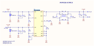
Here I am attaching schematic section of that part. Kindly reply to us as soon as possible as we can move forward in analysis and correct it.


Thanks, and regards,

Chauhan Mihir

  • Hello Ti Support Team,


    Waiting for response!

    Is there any limitation for negative input voltage for TPS2121?

    Is there any possibility of failing TPS2121 IC due to negative input voltage?


    Thanks, and regards,

    Chauhan Mihir

  • Hello Ti Support Team,

    We have simulated oring section in TINA-TI simulation software, which is suggested by TI only.

    So, we have simulated two different cases, and we have some queries that are listed below.

    Case -1: -

    IN1= -9V and IN2 = not given. so, we got simulation response which is shown in image1.

    Is this IC not supporting negative voltage?

    Case -2: -

    IN1= -9V and IN2 =5V. so, we got simulation response which is shown in image2.

    It gave 5V Output, so does it affect with reverse Polarity Supply?

    Case -3: -

    IN1= 12V and IN2= not given. so, we got simulation response which is shown in image2. It shows some parametric errors.

    We are confused regarding working range of IC. According to datasheet of IC, it should support up to 24V but as it is observed in simulation that t shows parametric errors.

    So, what will be actual working voltage range (Minimum voltage to Maximum Voltage).

    In other scenario, if we provide any reverse Polarity Voltage to IN1 then should it damage the internal structure of IC??  

    Thanks, and regards,

    Chauhan Mihir

    0880.Images.pdf

  • Hi Chauhan,

    Thanks for your patience, and sorry for the delay as we had a US national holiday yesterday. Welcome to e2e!

    TPS2121 can definitely be damaged by applying a negative voltage (less than -0.3V) to either input, or the output. I would recommend placing low Vfw diodes on the inputs, or using an ideal diode.

    The simulation model is defined for operation within the Abs Max conditions, which is why you are seeing inaccurate results when applying negative input voltages.

    Thanks,

    Patrick

  • Hello Patrick,

    Thanks for response and feedback on our comments.

    Any other comment for schematic which was already added in first conversion. 

    We used bidirectional TVS diode at input of IC Pins. So, there will be any chances to failure/ damage of Oring IC in near future if Customer used the wrong Adaptor...!!

    What are the chances of Failure for U2 IC with reverse Polarity Adaptor @9V – IN1.

    As per your evaluation board “TPS2121EVM-023” the D1 and D3 (MFR PN#: SMBJ20A-13-F) uni-directional diodes are used for preventing IC from negative voltage. So, the forward voltage of D1 & D3 are Vf = ±0.7V, and according to your response in our test case scenario the forward voltage of diode must be low as possible.

    So, can we use same diode with our circuitry which was used in your evaluation board. If not, then suggest us diode for preventing IC from negative voltage. It will be very help full for us to reduce down the U2 IC (PN# TPS2121) failure of the Unit.

    In other implication, based on your response bi-directional Diode is not suitable for PN#TPS2121, we must use uni-directional diode. Kindly acknowledge or correct if I miss understand any of this.


    Thanks,

    Chauhan Mihir

  • Hi Chauhan,

    As to your schematic, as you mentioned, I believe a unidirectional diode for overvoltage and a low Vfw diode for reverse polarity protection (like this) would be more applicable for the inputs. But I don't think you even need the overvoltage diode if there is no way the inputs will go above 22V, as the OVx will prevent higher-than-programmed voltages from propagating to the load. Also, D1 and D3 on the EVM are TVS diodes for preventing overvoltage and wouldn't be suitable for reverse polarity protection.

    There is also a very small chance that if the CMC was operating in the inductive frequency range, and if TPS2121's output went Hi-Z at the same time then there could have been an overvoltage spike on the output. But I think that since there may have been reverse polarity on the inputs that is much, much likelier.

    If there was -9V on IN1, I would say almost 100% chance of failure.

    I would also consider an ideal diode instead of a typical diode - it would be pricier but would have higher performance than a traditional diode.

    Thanks,

    Patrick

  • Hello Patrick,

    Thanks for response and your valuable comments for schematic.

    As per your suggestions, we are planning to change uni-directional diode (MFR PN #: LSM115JE3/TR13) from Bi-directional TVS diode for protecting our IC from reverse polarity/ negative voltage.

    Kindly acknowledge the details. So, we can move further for production. .

    Thanks,

    Chauhan Mihir

  • Hi Chauhan,

    Yes, that should protect the device. It would also be valuable to mention to customer to ensure the correct adapter polarity.

    Thanks,

    Patrick

  • Hello Patrick,

    Thanks for response and we will proceed with your valuable suggestion.

    My issue is solved as of now. I will connect you if further information is needed.

    So, I am going to close this ticket.

    Thanks,

    Chauhan Mihir