This thread has been locked.

If you have a related question, please click the "Ask a related question" button in the top right corner. The newly created question will be automatically linked to this question.

UCC28951: Load regulation disturbance

Part Number: UCC28951
Other Parts Discussed in Thread: UCC28950,

Dear Team,

We are designing power supply using PSFB controller UCC28951PWR.

Our specification is as below.

Input : 390V (From PFC) now not connected PFC section used DC source for testing.

Output : 24V @40A. i.e 960W.

Switching Freq. : 100KHz.

We are design the schematic with the help of datasheet and application note (UCC28950 600W Phase Shifted Full Bridge Design Review/Application Report (Rev. D)).

Now i am facing a problem in Load regulation, When we increase the output current (load) synchronous waveform disturb and variation output voltage.(i.e 24.56- 25.89VDC)

Condition :input 390V DC and output 24.56V DC at 15A,  above 15.2A observed disturbance some cracking noise from board.

Also observed heating at synchronous rectifier 85degree and the voltage at drain to source around 85V. (Transformer turns ratio - 10:1 inductance :1.6mH)

synchronous rectifier Specification : 100V, 130A, Rds 2.5mohm.

Regards,

Sudhir

  • Hello,

    Do you have waveforms and a schematic that you can share?

    Regards,

  • Dear Sir,

    Please find below file. 

    PSFB Schematic (2).pdf

    Yellow : Drain to source of A

    Green : Drain to source of B 

    Also we are facing another problem : if we switch off the 390VDC suddenly then Damage the output synchronous rectifier. I think there is problem in snubber ckt.

    Regards,

    Sudhir .

  • Hello,

    I am evaluating your inquiry and will get back to you shortly.

    Regards,

  • Hello,

    I reviewed your schematic and it appears that you are not using the discontinues conduction mode (DCM) SR FET shut off.  If you don't shut the SR FETs off before critical conduction the can develop a negative current, which can lead to excessive voltage across the FETs when they are turned off.  This is most likely is what is causing the crackling noise and your SR FETs to fail.

    The following link will bring you to an application note that goes through the step by step designing a phase shifted full bridge using the UCC28951.  There is a section on how setup the DCM comparator to prevent negative current going through the SRs.  There is also a link to an excel spread sheet that goes along with the application note that you can use to check your design.

    https://www.ti.com/lit/pdf/slua560

    Regards,

  • Dear Sir,

    sorry for the delay because board getting in repairing. 

    Yes, we enable the DCM mode and set the upper side resistor 18K. and checking the board performance.

    But, when the output voltage reached at 24V  then controller goes in protection mode.

    Regards,

    Sudhir Dhanawade

  • Hello,

    Did using the DCM comparator stop the FET from being damaged?

    Is the converter going into protection mode or light load burst mode?

    Regards,

  • Dear Sir,

    Did using the DCM comparator stop the FET from being damaged : We can't reach there...

    Is the converter going into protection mode or light load burst mode : Board going in Protection mode because driver A,B,C & D OFF when reaches 24V output.


    Regards,

    Sudhir  

  • Hello,

    Is this being caused by light load burst mode or over current protection?

    Both conditions will cause the outputs to turn off.

    Regards, 

  • Dear Sir,

    We enable the DCM and tested with load and it's working fine and regulate the output voltage.

    Here we set the 6A threshold current.

    But, below the 6A how to observed Fluctuation at output voltage. 

    How to tackle it? (Variation 24.0 - 24.8 reading fluctuating)

    Regards,

    Sudhir 

  • Hello,

    You might want to study the voltage amplifier output, CS, SS and the output voltage to see if you can figure out what is causing the output voltage to vary below 6 A.

    You also might want to check your Rtmin resistor to see where it is set.  Your controller could be going into light load burst mode causing the output fluctuation.

    Regards,

  • Dear Sir,

    Ok, will check that.

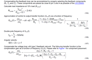
    Please help me to how to set and read the slop compensation equation. 

    In equation 107. mention the S(f) formula, so please help me to which value I consider for j. and f for switching frequency is it correct?.

    Regards,

    Sudhir


  • Hello,

    j is the square root of negative 1.  When it comes to S(f) this is referred to as angular velocity and is a function of frequency.  Gc(f) is the control to output transfer function.  The gain will move with frequency.  

    When it comes to setting up compensation you just need to use the cross over frequency for your design.  If you are using opto feedback this should be 1 to 2 kHz.

    Regards,