This thread has been locked.

If you have a related question, please click the "Ask a related question" button in the top right corner. The newly created question will be automatically linked to this question.

UCC24612: How to improve the efficiency

Part Number: UCC24612
Other Parts Discussed in Thread: LM358B


We are attempting to use 24612 for converting our existing DC-DC converter with flyback topology from diode rectification to synchronous rectification. Models are 12V 2.5A or 5V 6A. At present we are using the 24612-1EVM for trials on the low side.

R3 - 4.7R and C3 is 1000pf.

We are unable to boost the efficiency by any significant number.

The readings below is the end to end but does not include any bridge diodes.

Existing 12V Diode Rect 88% eff. With 24612 89%. Output power 24W.
Existing 5V Diode Rect 84%. With 24612 86.5%. Output power 17.5W.

The converter operating at 320Khz +/-10% dithering. We have tried to reduce to 250Khz. It has mitigated the shoot-through a little, but there is no noticeable improvement in efficiency. We have even attempted to use a 60V Mosfet with about 11mOhm RDS.

Using ST SRK1000 in a stock configuration, we find a 1%-1.5% efficiency gain over the 24612-1.

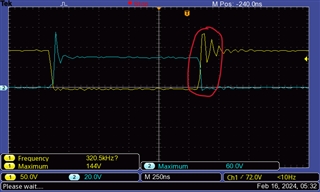
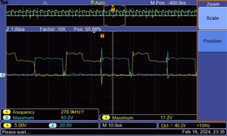
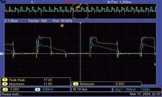
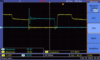
Enclosed two scope images. One is Vgs (yellow) vs Vds (blue) of the secondary FET Q1. The second is Vds Primary FET (yellow) vs Vds of Q1 secondary FET (blue) on the EVM.

Your thoughts on any parameters we can tweak to attain 91%+ efficiency? We really would prefer the TI part.

Thanks in advance.

Dave
  • Hello Dave, 

    To better help you, can you please provide more information about each application?

    The term "shoot-through" implies CCM operation.  Are they both CCM flybacks or DCM flybacks or one of each?  The waveforms appear to be CCM, but the test conditions are not provided, nor which board is being tested.

    Did you place the SRK1000 on the UCC24612EVM or separately on your flyback board?  Which design (12V or 5V) and which MOSFET was used with your efficiency comparison between controllers?  How was the ST part biased compared to the TI part?
    Did the ST circuit also have a 4.7R + 1000pF snubber across the SR MOSFET?   If not, can you retest the UCC24612 with the R-C snubber parts depopulated?  

    Neither waveform shows a complete switching cycle and each one indicates a different frequency (311.8kHz vs. 320.5kHz).  
    Is this from dithering on one board, or are these waveforms from 2 different boards?
    In any case, 311.8kHz has a 3.21us period. 

    The UCC24612 has a maximum turn-off blanking time of 3.68us which exceeds your longest switching period.   
    Although the turn-off blanking is adaptable, there may be cases where it extends beyond the switching period and the next SR gate-drive cycle is blanked to avoid shoot-through.
    Please check your SR gate-drive waveform to see if there are any missing pulses mixed in during steady-state running.  Missing pulses can account for lower than expected efficiency.
    If so, it is possible that the frequency dithering may be provoking the missing gate pulses.  Is it possible to disable the dithering and rerun the eff. tests? 

    Regards,
    Ulrich

  • Hi Ulrich

    Sorry for the delayed response. I was travelling.

    I will try and reply inline to your queries.

    1. We are in CCM. UCC24612 Eval Board on the Low Side.

    2.

    Below are some wave forms in 220KHz and 300Khz. Both are in full load conditions. IE Vin 48V. Output 12V 2A. Yellow is SR Vgs. Blue is Vds. Using Infineon BSC065N06LS5 on 24612 eval board. R3 - 4.7R and C3 is 1000pf.

    220KHz. No Freq Dithering. Vgs vs Vds on the SR.

    Sec VGs v VDs 48Vin 12Vout 220khz 24W no dithering.jpg

    300Khz. No Freq Dithering.

    Sec VGs v VDs 48Vin 12Vout 300khz 24W no dithering.jpeg

    300Khz. With Freq Dithering.

    300Khz with freq dithering. Output diode voltage waveform.

    voltage across output diode at Vin48V Vout 12V2A

    3.

    On our product board we changed the frequency resistor, and removed the LM358B driven frequency dithering circuit (+/- 10%).

    We see no change in the efficiency of the 12V model at either. We are testing the 5V model (5V at 4A to 5A) and will reply with those details.

    12V @ 300Khz. DC-DC 48.4Vin 0.567A. 12.02Vout 2A.

    Efficiency with Diode Vishay V20PWM60 on high side: 89.55%.  SR Efficiency with TI MosFET on Eval Board is 83%. Replaced with TI FET with Infineon BSC065N06LS5. Efficiency 87.6%. SR on low side.

    12V @220Khz. Under similar conditions using BSC065N06LS5 FET efficiency is 87.9%

    4.

    We used a daughter eval board from ST. SRK1000 (not the 1000A or 1000B). https://www.st.com/en/evaluation-tools/evlsrk1000-dp.html. On this board too we changed to BSC065N06LS5 FET.

    5.

    In our waveform, the max. off blanking time @220KHz is 2uS, @300Khz is 1.4uS, both of which are below the nominal value mentioned in 24612 datasheet 3.68uS.

    We see no missing pulse in the waveform. No change in efficency(with and without freq dithering).

    Conclusion

    It's very surprising that diode rectification is giving us better efficiency that SR. Your guidance is sincerely requested and most welcome.

    Thanks in advance.

  • Hello Devesh, 

    I need to study this some more and get back to you. 

    Regards,

    Ulrich

  • Hello Devesh, 

    I'm sorry I wasn't able to work on your SR issue yesterday.  I will concentrate on it today. 

    Regards,
    Ulrich

  • Hello Devesh, 

    Like you, I am surprised that diode rectification can give higher efficiency than SR.  
    The diode is in the high-side, while the SR EVM is added into the low side. 

    Am I correct to assume that you have shorted across the high-side diode when adding in the low-side SR?
    If you forgot to do this, then a small loss from the SR is added to the existing loss from the diode and efficiency will be lower than with the diode alone. 

    On the assumption that the diode IS in fact shorted out, it means that SR losses are higher than the diode losses.
    This might happen if there is some cross-conduction during the transitions between primary and secondary conduction intervals. 
    I think mostly if the SR turns off too slowly when the primary FET turns on.  
    It would indicate that the SR cross-conduction peak current or duration is significantly higher than the reverse recovery of the diode. 
    Please check for such cross-conduction current in the SR (a peak reverse current from drain to source).  

    Regards,
    Ulrich

  • Thanks Ulrich.

    Yes we have shorted the diode. Will revert with the peak reverse current from drain to source on the SR.

    Regards

    Devesh

  • Dear Ulrich

    Greetings. Apologies for the late reply. I was unwell and out of office.

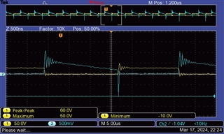
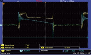
    Attaching three waveforms. We measured current through a 100mOhm resistor. So 1.04V is 10.4A. We used Infineon BSC065N06LS5 for SR. Datasheet. We removed the 100V FET mounted on the EV Board because performance was about 4% efficiency lower. Measurements are at 300KHz operation.

    Primary FET is FDD86252. Datasheet.

    1. Vds vs Cross Conduction Current

    Vds vs Cross Conduction Current 0.1ohm Resistor

    2. Vgs vs Cross Conduction Current

    Vgs vs Cross Conduction Current

    3. Vgs vs Cross Conduction Current Multiple Cycles

    The SR FET is faster than the Primary FET. Will welcome your thoughts on how to resolve this issue.

    Thanks in advance

    Dave

  • Hello Dave, 

    Thank you for the new waveforms and additional information.  

    In screenshots 1 and 2, you can clearly see reverse current peaks of about 10Apk at the moment when the SR FET turns off.
    The reverse currents are not clear in screenshot 3 because the oscilloscope sample rate is too low.  In my experience, a sampling rate of 10ns/sample or better provides good detail for faithful reproduction of the signal. 20ns/point is marginal, and any sampling slower loses a lot of resolution and waveform details.   

    Even if the SR FET is faster than the Primary FET, the SR turn-off is not fast enough to prevent significant reverse peak current.
    I believe that this is one of the major causes of lower-than-expected efficiency.  
    Because fSW is ~300kHz, I suggest to find an SR FET that is specifically designed for very fast body-diode reverse recovery. 

    Another contributor to loss is the ringing current at the turn-on of the SR FET.  I think this ringing comes from transformer magnetizing current resonating with secondary-winding capacitance.  It is probably not as much loss as the reverse peak generates, but still something to deal with. 
    I recommend to redesign the winding to minimize its self-winding capacitance.

    A third contributor is the narrower SR gate drive time on alternating cycles. I think there is some function within the UCC24612 controller that accounts for this. I think this function detects that the SR current is in deep CCM and changes the proportional drive to the -150mV Vds regulation threshold, as illustrated in Figure 18 of the datasheet.  But then the next cycle, the controller detects that the gate turn-off threshold has been reached about half-way through the SR conduction cycle and turns of the gate-drive early.  These two conditions seem to alternate on successive switching cycles.

    I'm not sure how to solve that behavior to make it stable from one cycle to the next.
    Since a 0.1R resistor is used to sense current, we see the SR FET conducts from ~0.6A (not counting ringing) down to about ~0.1A.  
    The  BSC065N06LS5 SR FET normally has an Rds(on) of 6~10mR at Vgs = 10V, depending on Tj.   
    In the case of the long Vgs pulses, clearly the proportional gate drive appears to be regulating Vds to either -50mV or to -150mV, so Rds(on) is high due to the low Vgs during the later part of the conduction time.

    But in the cases of the short pulses, Vgs = 9.5V and Rds(on) is near 6~10mV (estimated).  The short pulses turn off at Ids = ~0.4A, and 0.4A x 10mR = ~4mV.  -4mV is below the -9mV Vg turn-off threshold (Vthvgoff) in the Electrical Characteristics table.   
    I think this means that the MOSFET is simply too big (Rds(on) too low) for the current.

    I suggest to try using a MOSFET with higher Rds(on) AND fast recovery body-diode.  Low Rds(on) is not important, and ultra-low gate charge is not as important, but I believe that very fast diode recovery time IS important.  If Infineon does not provide one in your application range, maybe some other manufacturer does.  

    Regards,
    Ulrich