This thread has been locked.

If you have a related question, please click the "Ask a related question" button in the top right corner. The newly created question will be automatically linked to this question.

LM5176: IC heating

Part Number: LM5176

Hi Team

I've been testing our board with the LM5176 designed for the following parameters:

Vin: 19 to 30V
Vout: 25V/ 1A(cont.) and 5A(peak)

During testing (Vin:24.9V and NO LOAD) i observed the following:

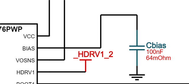
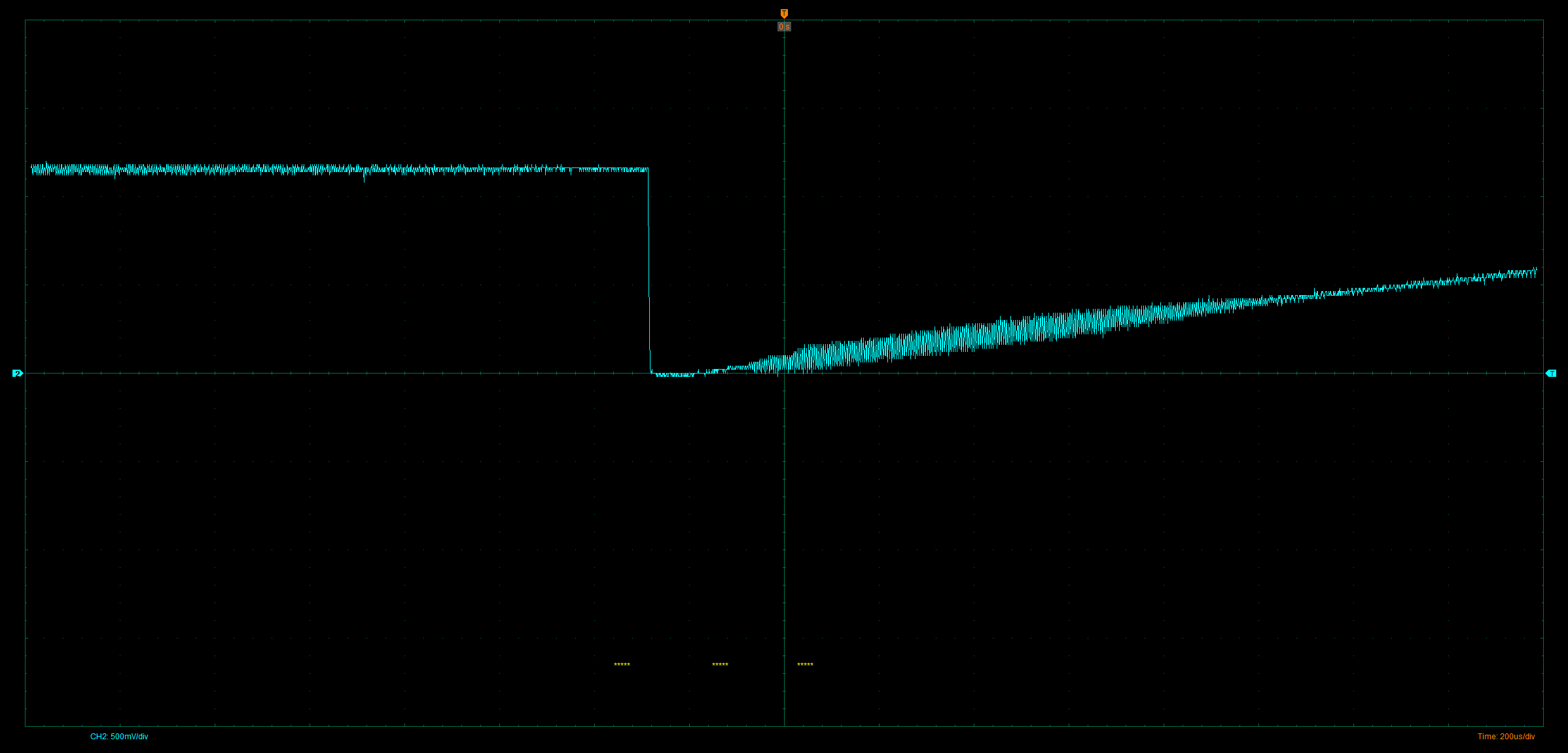
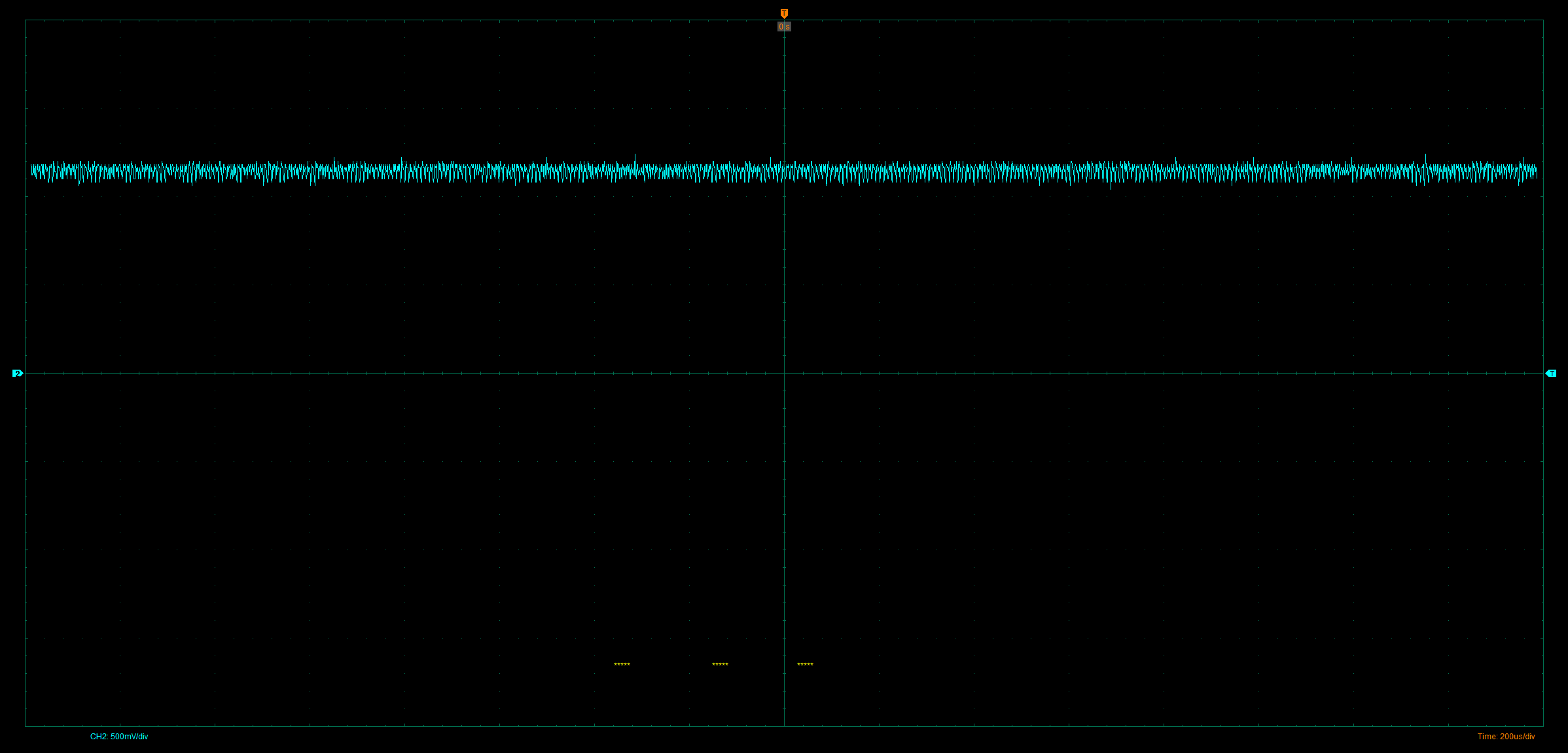
The board maintained good regulation during the initial moment when supply is connected and draws about 40-60mA (IC temp: 35deg.C @ ambient of 31deg.C)from the supply. But after a few minutes of keeping the board untouched in the same condition, the IC starts drawing about 110mA from the supply and heats to about 50deg.C (@ ambient of 31deg.C)  and loses regulation at the output. When the supply is disconnected and reconnected after a minute or 2, the IC restarts under the said normal conditions, but again starts drawing about 110mA after a few minutes of keeping the supply connected. I checked the VCC pin and noticed that initially when the draw is at 40-60mA, then the VCC is at 7.13V and when the draw increases to 110mA, the VCC falls down and jumps from 3.6V to 5.8V. 

Im not able to understand why this is happening. Please do look into this and let me know what are the possible problems that i may be facing and what can be a solution for this. 
I can share the Schematic and Gerber files on private chat for review if that would be necessary. 

Thanks and Regards
Noel Binny Abraham

  • Hi Noel,

    thank you for using the E2E forum.

    Is this the same board where you have shared the schematic some time ago or is this another one.

    How many boards have you checked? - do all show this behavior?

    If this is only one board please replace the LM5176 and check if it still shows this issue.

    Do you see this behavior only when you operate with no load?

    How is the behavior with normal load?

    When in the error case:

    Do you still see the expected output voltage?

    Can you check EN/UVLO, SS, and COMP pin? What signals do you have there?

    Best regards,

     Stefan

  • Hi Stefan
    Hope you are doing good.

    Is this the same board where you have shared the schematic some time ago or is this another one

    This is a newer board. I will share the files on chat with you again. Please do check the chat.


    How many boards have you checked? - do all show this behavior?

    If this is only one board please replace the LM5176 and check if it still shows this issue.

    I checked 2 boards. The first board that i had was fucntioning well for about 2 mins at 25V/5A on load, but an output capacitor ended up being shorted and my analysis was that it happened due to overhbeating of the board (Likely. I may be wrong. I have not identified a reason for this overheating though). Will replace IC and check and let you know.


    Do you see this behavior only when you operate with no load?

    How is the behavior with normal load?

    I see this behaviour on no load. I did not test it on load since i observed this issue during no load itself.


    When in the error case:

    Do you still see the expected output voltage?

    In the error case: I'll divide it into 3 cases:

    1. Buck mode (Vin>Vout): I do see the expected voltage at the output (25V±200mV) 
    2. Boost mode (Vin<Vout): I lose regulation and output drops down and jumps between 17V to 22V
    3. Vin approx. = Vout mode: Im not sure if im seeing a pass through or a regulation in voltage here but the expected output voltage is seen (25V±250mV)


    Can you check EN/UVLO, SS, and COMP pin? What signals do you have there?

    These look good and as per the datasheet values. They do not change when my supply current goes up from 40mA to 110mA. The only change i observed was in the VCC voltage.

  • Hi Noel,

    can you please replace the Boot Capacitors with a value of < = (Vcc Cap / 10)  e.g. 220nF or 100nF.

    Connect BIAS to VIN, VOUT or to GND (if not used)  -   will not fix this issue but would be better then have it floating.

    Best regards,

     Stefan - 

  • Hi Stefan

    I will change these Caps to 100nF ones and will update you.

    Ya ok. I used the Webench circuit here and added the 100nF (C15) Cap. I can short this pad. Again, will update you once i do this.

    Is there any possibilty that my IC is damaged? Since it is drawing so much current at NO-LOAD and the VCC voltage is dropping so much? But again, if this is true and my IC is damaged, im trying to understand the reason behind this as i do not want this to keep happening. Any suggestions on how i can understand the issues?

  • Hi Noel,

    i do not think - based on your description - that the device is damage.

    Nevertheless, esp. during initial debugging of a power stage a device can easily be damaged due to electrical overstress, e.g. due to over or undershoots on the switch nodes. So checking all nodes with a high resolution scope (500MHz or greater) is required to ensure that all parameters are kept inside the abs max ratings of all selected devices. Due to parasitic on the PCB and components this can not be generally predicted.

    This gets more critical, the higher the output current or the higher the voltages which are transferred in the power stage.

    Best regards,

     Stefan

  • Hi Stefan,

    Please do check your chat. I've shared the SW1 and SW2 node characteristics at Vin=24.9V and I_in=40mA and 110mA at NO-LOAD on output.

  • Hi Noel,

    looks OK - I do not see an undershoot but to ensure you should zoom in for a scale of ~ 20ns/div

    Best regards,

     Stefan

  • Hi

    So i just tested the boards again on load and observed the following:

    1.It was working as expected for upto 25V/2A.

    2.When i tested it for 25V and 3A, i observed that during the phase where Vin approx= Vout, the voltage dropped till around 23V and then got back into regulation when Vin reached around 22V.

    3.Same test when i did for 25V/4A, after the phase where Vin approx=Vout, the output regulation was completely lost and kept falling until 18V with reduction in Vin. So here the boost mode is not working at all.

    How do i troubleshoot this? I will share the testing reports for this with you on chat right away  

  • Hi Noel,

    what did you change now to get this working - now.

    Is my assumption right the it works in Buck Boost mode (Vin ~ Vout) with lower output current and only the output drops for higher output current.

    Can you check the SS pin in this operation mode?

    Thanks,

     Stefan

  • Hi Stefan,
    The bias pin was grounded instead of connecting it to a capacitor which is how i did it before.


    The only change i made was this.

    Is my assumption right the it works in Buck Boost mode (Vin ~ Vout) with lower output current and only the output drops for higher output current.

    Yes you are right, only drops for higher output currents (Above 3A, design is for 5A). But again it works fine when in buck mode and stops regulating at Vin approx=Vout and boost mode as shown in the Testing report i sent you on chat.

    Can you check the SS pin in this operation mode?

    As for the SS pin during boost mode for higher currents, At a Vin of 20V and 4A this is what i observed:


    And during normal operation (Buck mode, Vin= 27.7V and 2A output load), this is what i observed:


    Im using a 150W supply during this test.


  • HI Noel,

    can you check the voltage signal on the Current sense resistor at CS / CSG,
    Note: you need a very short probe connection - tip and Barrel method -see:

    Common Mistakes in DC/DC Converters and How to Fix ...

    -> shows Tip&Barrell - page 28

    Check if the peak voltage level is below the limit for the over current.

    Best regards,

     Stefan

  • Hi Stefan

    So i checked this and it is not going about 90mV in boost mode. Across the sense.

    I also observed that when i turn on the supply with a higher voltage (27V) and then start reducing input voltage to near Vout and lower than vout, i lose regulation, but if i turn on the the load of 5A at a Vin of 21V (i.e, boost mode) then the regulation works ok until 19.7V of Vin and then loses regulation again. This is a weird character that i observed today. 
    I will share a video of this on private chat for your reference 

    Thanks and regards
    Noel

  • HI Noel,

    have you already tired to reduce the sense resistor and check out if this changes the behavior.

    If not please do so, to ensure the current limit does not get triggered.

    Best regards,

     Stefan

  • Hi Stefan,

    This did resolve my issue. My IL_peaks were going above the set values. I changed the current 12mOhm sense to 5mOhm and this seems to be working well for me. Will update if there are any other problems during testing.
    Thanks for your help! 

    Best Regards,
    Noel