This thread has been locked.

If you have a related question, please click the "Ask a related question" button in the top right corner. The newly created question will be automatically linked to this question.

BQ25120A: TS fault error

Part Number: BQ25120A

Hi Team,

We are using bq25120A in one of our projects.

See the circuits below:

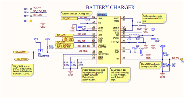
We are getting the TS fault error, ie, on 02h, we are getting e8 and a8 in normal working temperature(25deg.c).

We tried disabling TS functionality by putting R5=6k and R19=12k and R20 as DNM.Still we are getting error. 

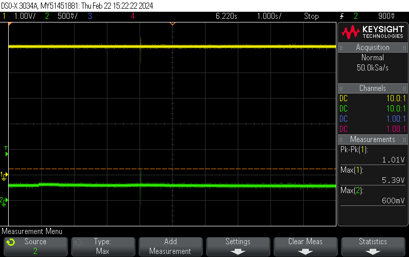
When the issue occur the TS voltage is observed as less than 0.9V or grater than 1.8V

Can you please suggest what could go wrong here.

Regards,

Jenitt 

  • Hi Jenitt,

    It appears that the TS voltage detected is above or below the TS warm and TS cool voltage thresholds, though this is being read at 25C. Can you confirm your NTC's properties (Beta value and calibrated resistance) so that I can calculate the expected behavior across temperature?

    If you force a voltage on TS you shouldn't see any TS fault between 20.8% of VIN and 35.4% of VIN. Can you confirm this is the case on your charger?

    Best Regards,

    Juan Ospina

  • Hi Juan, 

    Thank you for your prompt response.

    Above is the Electrical characteristics for B-Value 
    Calibrated resistance are RHI=30k and RLow=64.9K and NTC=10K

    Case-1
                             We removed NTC and used Fixed 10k Resistor 
    But we still see the Fault state i.e.. 0x02h =e8 or a8 and TS Pin we see voltage variation between 0.2v to 0.9v or Greater than 1.8V

    Case -2
    We mounted NTC Outside our board and connected using a wire (suspected NTC Issue but not)
    But we still see the same fault state and TS Pin we see voltage variation between 0.2v to 0.9v or Greater than 1.8V

    Case-3
    We tried disabling the TS using Register change 0x02h(7th bit) here We removed ntc 10k DNM and mounted only Rhi=30k and Rlow=68.1K(voltage calculated divider output should be 3.44v and VIN=5v) But we see voltage varying from 3v to 4v. TS is disabled but there is voltage variation at TS pin point. 

    Case-4
    We tried disabling TS pin by only resistors(Rhi=30k and Rlow=68.1K expecting output of divider be 3.44v which is more than 60% of Vin)NTC is DNM
    But we see voltage here at the varying from 3v to 4v.

    Can you please go through the above cases and please let us know what might the issue ? 


    Thanks, 
    Muhafeez

  • Hi Muhafeez,

    The TS pin only has voltage sampling circuitry so voltage variation is due to your pull up rail (VIN) and resistor values. Can you share a waveform of VTS and your Input voltage as well?

    Best Regards

  • Hi Juan,


    Thanks for your reply, 
    Please find attached waveforms-


    Green- VTS PIN(500mV/Div)
    Yellow- 5v VIN(1V/Div)

    Our Vin is regulated and it is stable at 5V and resistor(Rhi=24.9k and Rlow=40.2K with NTC 10K) we also checked the resistor values and We removed thermistor mounted Fixed 10K, The Behavior is same. 
    We notice VTS Drop from 1.26V to 300mV after keeping the device on and in charging state for 15 mins 
    We suspect something is going wrong on BQ25120A TS. 

    Kindly Let us know your inputs and suggestions.  

    Thanks, 
    Muhafeez 

  • Hi Juan, 

    Any update? Can you please let us know?


    Thanks,
    Muhafeez

  • Hi Mahesh,

    Apologies for the delay. The VTS behavior is certainly unexpected since voltage at TS should be purely determined by your VIN and the resistors used across the resistor divider. The BQ25120A should not be exerting any kind of voltage or current on the TS pin, only sampling the voltage. This is especially unexpected with a fixed resistor since voltage should never really change. If there are no other paths to this node via which this it can be biased, and if there isn't a possible soldering or contact issue then I would suspect the device may be damaged. 

    Is this behavior you are seeing on multiple devices and boards?

    Best Regards,

    Juan Ospina

  • Hi, 

    We have cross checked  the board and there is no issue with soldering. All boards  are assembled at PCB SMT factory only. 

    Also noted this in  issue  multiple boards. 

  • Hi Mahesh,

    Are you able to have IC's re-balled and soldered? I'd like to check this behavior with one of these units on an EVM to confirm that it is something caused by the ICs. 

    Best Regards.

  • Hi, 

    Now onwards I am taking responsibility of this case. 

    IC's re-balling is not possible at my SMT assembly house because of limitation. Moreover, soldering more than two times is not possible because, the Rigid flex PCB thickness is 0.4MM only. 

    For do failure analysis, we had shipped ICs ( 2 nos) to Texas Instruments, Germany. 

    In between, I have one query.

    1. What is the current consumption of BQ25120A TS pin? 

    2. With divider network resistors of 24.9K and 40.2K, the current allowed flow is =5V/65.1K =77uA only. Is this okay for TS pin functionality? 

    Regards

    Sudheer

  • Hi Sudheer,

    The current consumption of the TS pin should be minimal since inside are only comparator input circuitry. I will have to look for an exact number.

    This current flow should be fine, the TS function at this device cares mostly about the voltage so it s a high impedance input and does not require a lot of current to function.

    Best Regards.