Other Parts Discussed in Thread: STRIKE
Hello TI Engineers,
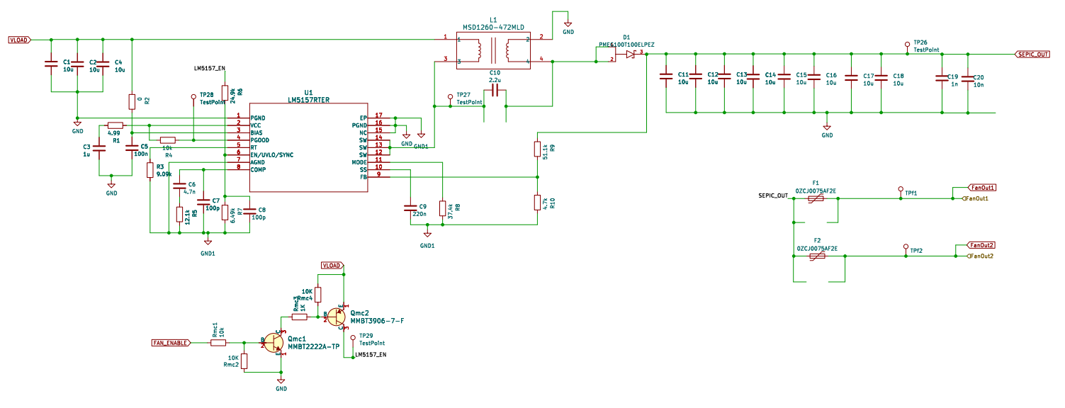
I was using my LM5157 SEPIC circuit when all of a sudden it stopped working. The schematic is shown below and the layout is very similar to the LM5157 SEPIC Evaluation Board. The LM5157 circuit is a subcircuit on a a main mixed signal design board. I have used the board for a couple of days and have been using it regularly for testing. The Input Voltage, VLOAD is 9-15V. The output, SEPIC_OUT is set to 12V. The LOAD is a 12V 2-wire fan and a number of LEDs and 2 Relays that draw a maximum current of just over 1A.
The first thing I noticed was the LEDs and FAN stopped working. I probed the SEPIC output test point and saw no Voltage in the Multimeter. There were no shorts on the LOAD side. There was a high current draw on the power supply. The LM5157 is enable is controlled by a PNP transistor Qmc2 which is controlled by a microcontroller PIN, FAB_ENABLE. VLOAD is always connected to the LM5157 circuit/ I first removed the LOAD connected to the LM5157 and Enabled it. There was still no voltage on the output (SEPIC_OUT).
EN pin is getting the correct voltage when Qmc2 is ON. Then I probed the the VCC pin and measured 0V. Measuring the other good boards I have, the LM5157 VCC pin is measuring 5V when enabled. I removed R1, 4.99Ω to see whether that was causing the short, but the VCC to Ground short remained after removing the resistor.
Would you happen to know what might cause only VCC to get shorted to ground? The Input, Output, BIAS do not show any issue. They are not shorted to ground. There are also no issues with the LOAD since I was able to use it on another board with a good LM5157 circuit.

Thanks,
Deniel