This thread has been locked.

If you have a related question, please click the "Ask a related question" button in the top right corner. The newly created question will be automatically linked to this question.

LP2981A: ESR Capacitor in parallel with decoupling

Part Number: LP2981A
Other Parts Discussed in Thread: SN6501,

Hello TI team,

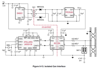
I need to implement an isolated CAN Bus node based on the spec sheet recommended design of the transformer driver SN6501.


Question 1

I would like to use the LP2981A-50DBVR 5V LDO regulator for this application instead of the TPS76350-Q1 which has a current limit that is too high for my needs (800mA typ). Indeed, the LP2981A-50DBVR 5V LDO regulator has a low current limit which is appropriate for my application (150mA typ). The spec sheet for the LP2981A-50DBVR LDO regulator recommends to add an effective output capacitor (4.7uF) with some ESR for loop stability.  I would like to use ceramic capacitor instead of tantalum.  The spec allows the use of ceramic capacitor if a 1ohm resistor is added in series with the capacitor. So, giving that the CAN transceivers (TCAN1051HGDR ) and signal Isolator (ISO6721BDR) will both have ceramic decoupling capacitors on their power pins, will these decoupling capacitors cancelled the ESR of the provided capacitor+resistor arrangement at the output of the regulator?  Will all the ESR of the ceramic decoupling capacitors parallel since all the components are very packed on the isolated side?

Question 2

In order to get 4.7uF of effective capacitance, 2 capacitors need to be installed in parallel to get this value because of ceramic capacitor DC bias.  If more than one capacitor is used at the output of the regulator, is the series resistor need to be spitted? 2ohm added to one capacitor and 2ohm added to the other capacitor?  Can the total resistance be added to one capacitor only?     

Question 3

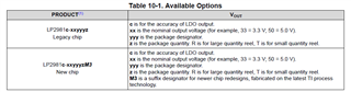
 The LP2981A spec keeps referring to this “new chip” which has better dropout voltage and is stable with low ESR ceramic capacitors.  The IC has a “M3” suffix.  Is this IC available?

 Thank you,

 Regards

 Eric


  • Hi Eric,

    Question 1

    The capacitor ESRs don't exactly parallel, but the impedances do. To illustrate how the impedances combine, I pulled a 0.1uF capacitor (randomly picked) from Murata's Simsurfing tool and used the PSPICE model for the capacitor to simulate it along with a 4.7uF capacitor with a 1Ω series resistor - see the simulation results below (red = 0.1uF, green = 4.7uF + 1Ω, yellow = parallel impedance of both). As you can see, the 4.7uF capacitor dominates the impedance curve at lower frequencies since the 0.1uF capacitor is such high impedance at those frequencies, and once the 0.1uF impedance falls below the 4.7uF impedance, the 0.1uF impedance dominates. What's important is that the 1Ω series resistor keeps the impedance high enough within the bandwidth of the LDO, which is typically less than a few hundred kilohertz. So, as long as the decoupling capacitors for the other devices have resonant frequencies above 1MHz or so, the LDO doesn't care. 

    Question 2

    The datasheet recommended capacitors already assume 50% derating due to DC bias, so using a single 4.7uF capacitor (for the legacy device) plus a 1Ω series resistor is acceptable. If you still wanted to put 2 capacitors in parallel, a single series resistor with the multiple capacitors in enough.

    Question 3 

    The nomenclature table for this device is actually incorrect. The orderable names for the redesigned devices will not have an "-M3" suffix; the device names are unchanged. Right now we are in the transition period where orders for this device may be result in getting old devices or new devices, and there's not a lot we can do ahead of time to know which one you'll receive. Once supply of the old devices is through, all devices will be the new chip. 

    Regards,

    Nick