This thread has been locked.

If you have a related question, please click the "Ask a related question" button in the top right corner. The newly created question will be automatically linked to this question.

UCC21750: The variations in the DESAT detection threshold and capacitor charge current values.

Part Number: UCC21750

I'm in the process of designing a gate driver, and I have a quick question.

1- Should we use typical values for "detection threshold" and "capacitor charge current" from the technical document?

Please correct me if I'm wrong, but I believe the variability in these values is due to temperature. However, when planning for normal operation at 50 degrees junction temperature, for example, which values should I consider?

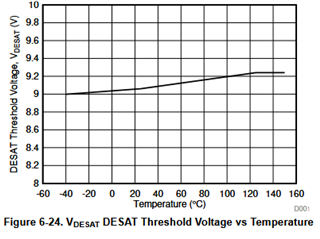
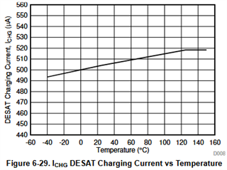
My concern stems from the potential discrepancies in calculation results. For instance, there can be a difference of 0.7 μS between the minimum and maximum "capacitor charge current" values. Or, as another example, there's a 1-volt difference between the minimum and maximum "detection threshold" values, which translates to a difference of 100A-150A for the 2MBI150VA-120-50 IGBT I'm using.

Could you help clarify my confusion on this matter?

Best regards,

  • Hi,

    Thank you for posting to E2E.

    The tolerances provided on the datasheet account for part-to-part and temperature variation. In other words the min and max values are the worst case conditions at their respective temperatures. For an application with expected junction temperature of 50C I would recommend to use the typical values for calculations.

    I would also like to mention that besides the tolerances of these values the design of your system itself will have a great impact on the over-all short circuit transient(over current amplitude, dI/dt, resulting overvoltage, dV/dt, etc...) and detection timing. For this reason the DESAT circuit has to be calculated using the equations provided in the datasheet, but must be fine tuned in the final system by running short-circuit/over-current tests.

    Last thing I would like to mention is that typically IGBTs are a more forgiving technology for short circuit protection than other technologies such as SiC MOSFETs. The short circuit current amplitude can quickly exceeds 100s of amps and can IGBTs can typically withstand the short circuit transient for longer durations of times(I've see 3us-10us). I would highly encourage you reach out the IGBT manufacturer and get additional information for short circuit withstand capabilities which don't seem to be included in the datasheet of the part number you provided.

    Best regards,

    Andy Robles

  • Hi,

    Thank you for your quick response.

    In your reply, you mentioned that the "detection threshold" and "capacitor charge current" values can vary from component to component. Of course, I understand that identical components from the same model may not be exactly identical in every aspect in real-world designs, such as slight variations in output resistance. However, we usually ignore such negligible variations for practical purposes.

    However, if the variation in values shown in the figure represents the minimum and maximum values for component-to-component, wouldn't this imply that we need to perform desaturation tests repeatedly for each produced unit?

    I am asking the question, but most likely, I will calculate based on typical values and make adjustments according to its practical response. However, I am concerned about the variability in values in repeated productions. I want to know the main reason for these variations in the "detection threshold" and the "capacitor charge current" values. For example, if it is ambient temperature, and if it is possible I also want to know which direction the values will change as the temperature increases.

    Thank you very much for your support.

    Regards,

  • Hi Harun,

    We test these parameters to produce a standard deviation curve at each temperature with 25C being the typical. The 6 sigma outlying limits of the HOT and COLD are what give us the min and max values provided in the datasheet. In other words the biggest variation delta is due to temperature.

    Best regards,

    Andy Robles

  • Hello Andy,

    Thank you for your help.

    If I misunderstood, please correct me, then the increase in temperature will cause the "detection threshold" and "capacitor charge current" values to move towards the minimum values.

    Best Regards,

  • Hi Harun,

    In our datasheets we include graphs across temperature for critical parameters for you to be able to see the trend across temperature. For UCC21750 it is section 6.12 Typical Characteristics.

    In this section of the UCC21750 datasheet you can find the graph of the DESAT threshold vs temperature (Figure 6-24) and charging current (Figure 6-29). These graphs use the mean of each parameter at each temperature (-40C, 25C, 125C, and 150C) to show the typical characteristics across temperature.

    Both DESAT threshold and charging current approach the move towards the max values with increase in temperature.

    Best regards,

    Andy Robles

  • Hi Andy,

    Thank you so much for your help.

    Best Regards,