Hello,
Issue up front: the default recommended connection for VC0 does not work for external balancing of cell 1.
I am having an issue with cell balancing on a design using the BQ76952. The design has external balancing as described in the SLUAA81A App Note. I mistakenly used 1k ohm filter resistors instead of the 100 ohm recommended values as I was following the SLUA420A App Note. That being said, I don't believe it is contributing to the issue I am having.
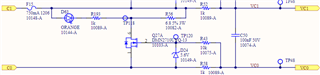
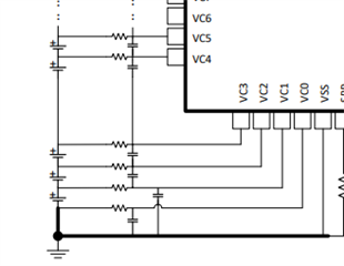
The cell balancing circuit for C1 was powered while the rest of the design was not powered by providing a voltage only across V1 and V0. The VC1 and VC0 nodes were shorted together to mimic the internal FET closing on the AFE (which was unpowered at the time). It was observed that the voltage Vgs was lower than expected. After a time it was discovered there was an additional element to the divider in the form of the resistor from VC0 to GND that is called out on page 66, 67, and 75 of the BQ datasheet.
This resistor as stated makes it much more difficult to balance the lowest cell during operation, and is strictly different than all other cells in this way, as imbalanced cells above cell 1 do not have an additional element in the divider. Is the resistor to GND necessary as there is already a filter resistor from VC0 to C0? As far as I can tell I am mimicking the design as expressed in the datasheet, but please correct me if I am wrong. GND is BATT-, C0 and BATT- are shorted externally on the harness battery-side.
I do not understand how the balancing is supposed to function if this is the required configuration.