Other Parts Discussed in Thread: TPS92621-Q1
Hello Team,
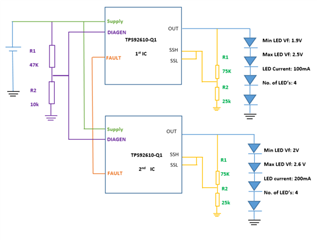
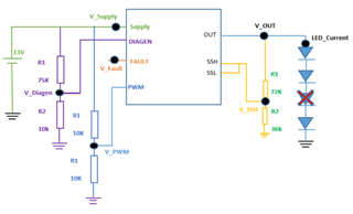
We are currently using TPS92610-Q1 (Single-Channel Linear LED Driver) in one of our designs.
The operating temperature range is -30°C to 85°C for our design. We have downloaded the TPS IC spice model from the TI website which is operating only between -10°C to 25°C.
1) Could you please share the TPS92610-Q1 spice model which operates at -30°C to 85°C.
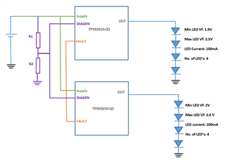
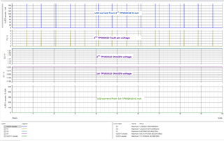
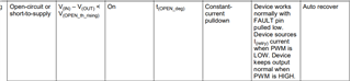
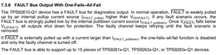
2) Also, please confirm is it possible to connect two or more Fault signals together for One fail all fail detection if the Rp resistor is used.
Regards,
Mohammed Khalif