Hi,
Would you please help review for below LM51772 schematic?
Vin = 48V
Vout = 5V/9V/12V/20V/24V/48V
Iout = 5A
Thank you!
Jeff
This thread has been locked.
If you have a related question, please click the "Ask a related question" button in the top right corner. The newly created question will be automatically linked to this question.
Hi,
Would you please help review for below LM51772 schematic?
Vin = 48V
Vout = 5V/9V/12V/20V/24V/48V
Iout = 5A
Thank you!
Jeff
Hi Jeff,
Thanks for reaching out. We'll get back to you with some feedback by today.
Thank you and best regards,
Bryan
Hi Jeff,
Thanks for waiting. Could you please attach the filled out LM51772 BuckBoost Quickstart Calculator Tool?
This would greatly help us achieve a proper evaluation of the schematic to make sure it's right for your application.
Thank you and best regards,
Bryan
HI Jeff,
as you can see for the 48V the inductor gets to small - you should select the 6.8uH.
This would be good also for the 48V.
Do you need the 5A also for 5V output - usually this is less for USB-PD.
I assume you will control the output voltage via I2C:
In this case FB-IN should be connected to AGND and FB to VCC2 - this enables the internal FB divider which can be controlled by I2C
Connection of DRV1 does not work the way it is connected but components are DNP - so not critical as long as this function is not needed.
Resistor at CFG1 does disable I2C - please check
All connections with the light green rectangle and TP_xxx are unclear - ensure this have the proper connection and components.
Note: cap at VCC2 needs to have the value from the Datasheet with considering DC-Bias.
Note2: AGND and PGND need connection point at Thermal pad
Excel sheet shows Iimiter and CDC of but components are place - please check again - also check required components at CDC and ILIMCOMP pin.
Best regards,
Stefan
Hi Stefan,
I would like to ask C26/C27 50V is enough for 48V design?
May I need choose 100V to get more design margin?
Thanks!
Jeff
Hi Stefan,
Still have some question need check with you.
1. If FB pin no need connect to external divider resistor, how to LM51772 check Vout voltage? Via pin19 ISNSN/(VOSNS)?
2.CFG1 connect to VCC2 dierectly? or need a pull high 10k or 100k resistor?
3. AGND and PGND if using 0ohm connect to each others, which size do you recommend? or how many current rating for this connection?
4. SYNC and DTRK connect to VCC dierectly? or need a pull high 10k or 100k resistor?
5. For inductor have any DCR limitation? Now we found 6.8uH DCR about ~23mohm, is it okay? any side effect?
Thanks!
Jeff
HI Jeff,
see my comments using your numbering:
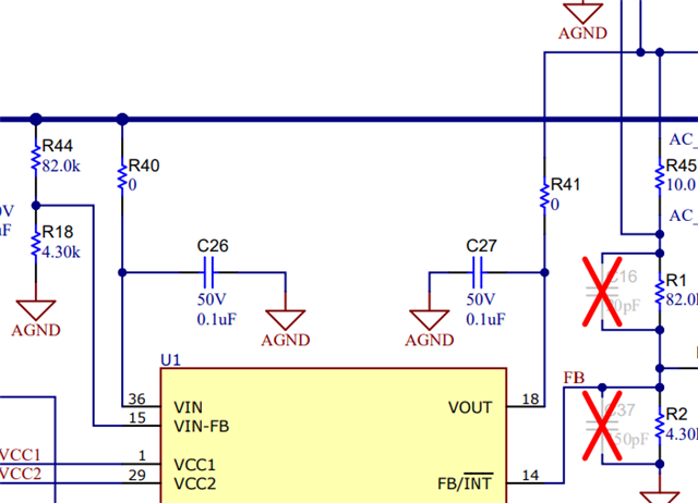
1, if using the internal FB divider (Selected by FB connected to VCC2) the internal FB divider is used - internally it is connected to VOSNS.
2. If setting16 should be used for CFG1 you can use a resistor of 36.5k or connect to VCC2. I recommend to use the resistor so you can change the setting if required.
3. AGND and PGND should be connected via the thermal pad - no resistor - see also EVM layout
4. SYNC and DTRK can be connected to AGND or VCC2 directly.
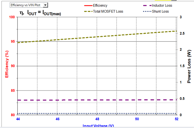
5. The DCR of the inductor increase the loss in the inductor. So if you can handle the heat generated in the inductor and the efficiency is meeting your target then it is OK. You can see the estimated losses of the inductor in the quickstart calculator as well.
Best regards,
Stefan
Hi Stefan,
Sill have have question on item 5.
I using the calculate tool to fill about 25mohm inductor DCR, but can't find Efficiency red line as below.
We want check the Efficiency diff for the inductor DCR.
0537.LM51772_Buck-Boost_Quickstart_Tool_V1_1_0 (2).xlsm
And we choosing below 80V MOSFET is fine? Anything need notice?
Thanks!
Jeff
Hi Stefan,
If my d1esign change to input 36V, is it possible reduce for inductor value?
Also can reduce input/output capactior? or suggest keep as 48V design?
8816.LM51772_Buck-Boost_Quickstart_Tool_V1_1_0 (2).xlsm
Thanks!
Jeff
HI Jeff,
sure, you can make the inductor smaller. Ensure it does not get marked red in the inductor field.
When asking for reducing the capacitor - do you mean the voltage rating or the capacitance.
Voltage rating should be ~ 30% above the max voltage on the cap.
Capacitance: depends on the the required ripple you can allow.
Best regards,
Stefan