A related question is a question created from another question. When the related question is created, it will be automatically linked to the original question.
If you have a related question, please click the "Ask a related question" button in the top right corner. The newly created question will be automatically linked to this question.
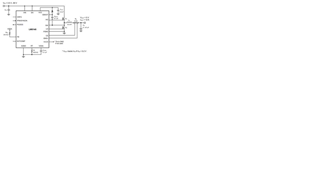
Thank you for filling out spreadsheet. Looks like you have designed your circuit to meet your requirements. suggest you pay attention to adequate damping as detailed in the datasheet if you are using an input filter. also make sure you pay close attention to the layout guidelines as detailed in the datasheet. hope this helps.
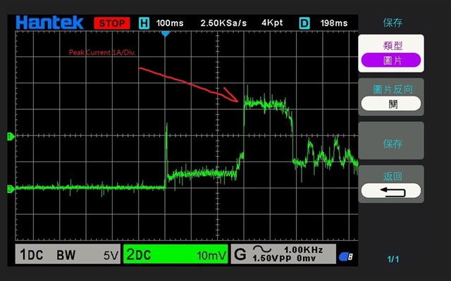
The input capacitor next to it is 150uFCustomers mainly want to know, when the input voltage is equal to or less than the output voltage, the output voltage can be down or pass-through, but the output must be able to work at 4A (waveform below)Is this condition feasible?
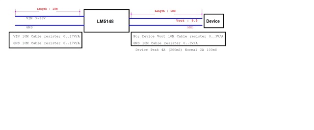
customer system Power in Cable length(10M) and Vout connect Cable length (10M) , plz refer attached file . Device P-on current waveform
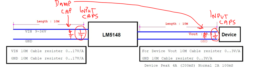
You will need damping capacitors at the end of each cable length. Also pay sloe attention to the capacitors ESR, it's the ESR that provides the damping. the amount of damping resistance will depend on the parasitic inductance of the cable and the ceramic capacitors using Sqrt(Lp/Cceramic). for the input, assuming you have a effective capacitance of 4.7uF and a parasitic inductance of 1uH, will need an ESR of ~0.5ohm.
Also, yes with a correctly designed circuit with adequate damping, it should be able to provide an output voltage very close to the input voltage with 4A of output current. Hope this helps.
Damping capacitor needs to be at least 4x higher capacitance than the ceramics (derated) its damping. suggest 47uF damping capacitor. can adjust Rdamp to suit once on the bench.
make sure you add damping cap at input, if you also have long cables to the input to power stage.
The following are the modifiy suggested by customers, please help to confirm
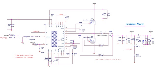
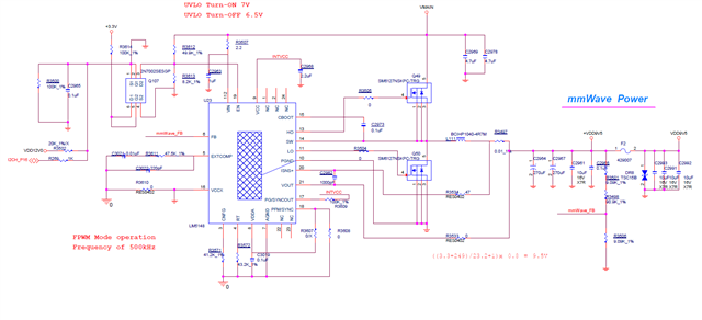
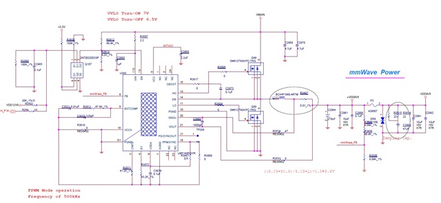
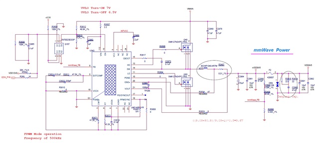
1. According to the specification formula and MOS tube parameters, Q49 will overheat when powered by 36V. It is recommended to reduce the switching frequency from 500KHz to 150KHz (R3572 is adjusted from 43.2K to 147K Ohm)
2. Because Toff_min=90nS, the input voltage range is 9~36V and needs to be adjusted to 10~36V
3. According to the specification requirements, the value of Rfb2 is 10~20K Ohm. It is recommended to adjust the R3506/R3498 from 9.09kOhm to 10k Ohm; R3501 from 90.9kOhm to 100k Ohm;
4. According to the formula in the specification book, adjust the current sensing resistor R3497 from 10mOhm to 5mOhm.
5. According to the specification formula and MOS tube parameters, C2973 is adjusted from 0.1uF to 0.22uF
6. According to the formula in the specification, adjust the input capacitor C2969/C2978 from 4.7uF/50V/X7R to 10uF/50V/X7R, and add three 10uF/50V/X7R capacitors
7. According to the formula in the specification, the compensation resistor R3611 is adjusted from 47.5K_1% to 22K OhmCompensation capacitor C3021 is adjusted from 0.01uF to 3300 pFCompensation capacitor C3022 adjusted from 220pF to 20 pF
Will need to put in your inductor value with your specification in the design calculator and ensure you are using close to the recommended inductance therein.