Part Number: BQ76952
Hi
I am using a BQ76952 board. I am current working on Current Calibration using the AFE board. I am having trouble reading CC2 & CC3 counts. I am reading the counts using ReadDASTATUS5() subcommand. The values that I am getting seem to be quite huge. I am using a sense resistor of 0.25 mV. So based on the formula CC Gain = 7.5684 / (Rsense in mΩ) The calculated value for CCgain = 7.5684/0.25 = 30.2736 which in terms of IEEE floating point format is 0x41f23055. Whereas since the Capacity Gain is CC Gain multiplied by 298261.6178. I got a value of 30.2736 * 298261.6178 = 9029452.91263008 (which is 0x4b09c74d in Hex).
To proceed further with any kind of calibration steps mentioned in the Calibration and OTP Programming Guide, I should have a kind of correct CC2 count value. As all the calibration steps involve averaging of CC2 counts value. I tried taking multiple CC2 counts value at multiple instances. But it gave me a value similar to the one shown below.
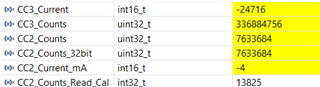
Based on the code the CC2 counts value that I am getting is:

The above value seems to be wrong based on what the sample code in the BQ769x2 Calibration and OTP Programming Guide says. Can someone please verify the code?
Here is my configuration setting:
AFE_SetRegister(DAConfiguration, 0x03, 1);
AFE_SetRegister(CCGain, 0x41f23055, 4); // (Unit userA)
AFE_SetRegister(CapacityGain, 0x4b09c74d, 4);
AFE_SetRegister(CC3Samples, 0x50, 1);
Here is my code to read CC counts:
void Subcommands(uint16_t command, uint16_t data, uint8_t type)
// See the TRM or the BQ76952 header file for a full list of Subcommands
{
//security keys and Manu_data writes dont work with this function (reading these commands works)
//max readback size is 32 bytes i.e. DASTATUS, CUV/COV snapshot
uint8_t TX_Reg[4] = {0x00, 0x00, 0x00, 0x00};
uint8_t TX_Buffer[2] = {0x00, 0x00};
//TX_Reg in little endian format
TX_Reg[0] = command & 0xff;
TX_Reg[1] = (command >> 8) & 0xff;
if (type == R) {//read
I2C_WriteReg(0x3E,TX_Reg,2);
HAL_Delay(2);
I2C_ReadReg(0x40,RX_32Byte,32); //RX_32Byte is a global variable
//I2C_ReadReg(command, RX_32Byte, 32);
}
else if (type == W) {
//FET_Control, REG12_Control
TX_Reg[2] = data & 0xff;
I2C_WriteReg(0x3E,TX_Reg,3);
HAL_Delay(1);
TX_Buffer[0] = Checksum(TX_Reg, 3);
TX_Buffer[1] = 0x05; //combined length of registers address and data
I2C_WriteReg(0x60, TX_Buffer, 2);
HAL_Delay(1);
}
else if (type == W2){ //write data with 2 bytes
//CB_Active_Cells, CB_SET_LVL
TX_Reg[2] = data & 0xff;
TX_Reg[3] = (data >> 8) & 0xff;
I2C_WriteReg(0x3E,TX_Reg,4);
HAL_Delay(1);
TX_Buffer[0] = Checksum(TX_Reg, 4);
TX_Buffer[1] = 0x06; //combined length of registers address and data
I2C_WriteReg(0x60, TX_Buffer, 2);
HAL_Delay(1);
}
}
void AFE_ReadDASTATUS5()
{
Subcommands(DASTATUS5, 0x00, R);
CC2_Counts_32bit = ((RX_32Byte[27]<<24)+(RX_32Byte[26]<<16) + (RX_32Byte[25]<<8) + (RX_32Byte[24]));
CC3_Counts = ((RX_32Byte[31]<<24) + (RX_32Byte[30]<<16) + (RX_32Byte[29]<<8) + (RX_32Byte[28])); //Bytes 8-11
CC3_Current = ((RX_32Byte[21]<<8) + (RX_32Byte[20])); //Bytes 8-11
}
The charging current I applied is approximately 1 ampere, but the CC2 value significantly differs from the applied charging current. I am uncertain where the issue lies and would appreciate your guidance.
Regards,
Satvik Pai