This thread has been locked.

If you have a related question, please click the "Ask a related question" button in the top right corner. The newly created question will be automatically linked to this question.

BQ25792: BQ25792 after the battery is fully charged there is still 38mA discharge

Part Number: BQ25792
Other Parts Discussed in Thread: BQ25798

Hi 

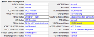
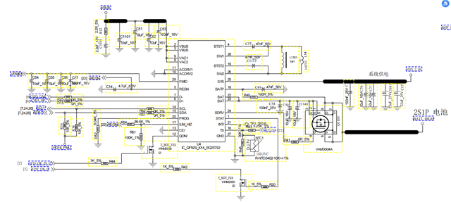
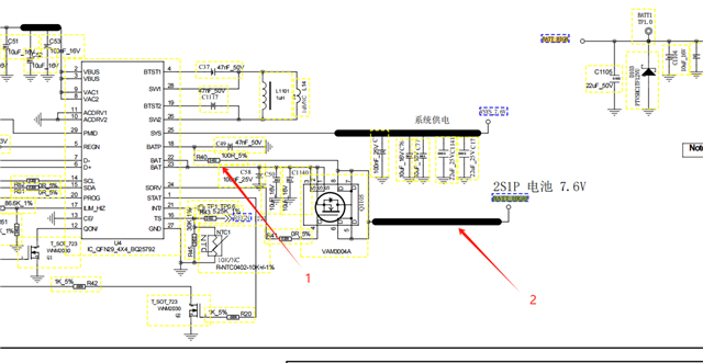
The customer design with BQ25792.

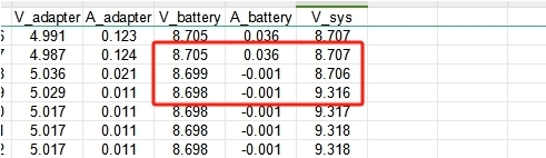
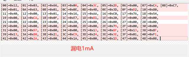
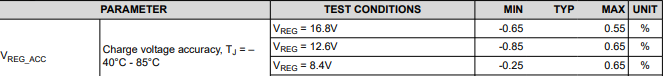
The battery is not turned off after it is fully charged and charging is stopped. There is still a current output of 38mA. There are also cases where the battery has a leakage current of 1mA after charging is stopped. Can any problems be detected by measuring the signals of the following two phenomena? When charging is stopped, the SYS voltage will jump from equal to the battery voltage to 0.6V higher than the battery voltage. Is this normal?

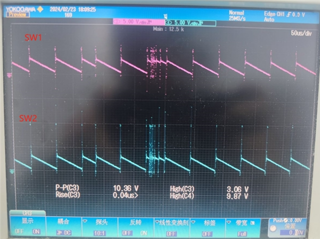
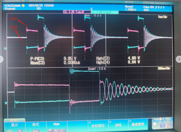
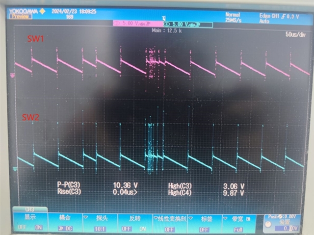
The measured waveforms of sw1, sw2, V_bat, and V_SYS under the two phenomena are as follows:

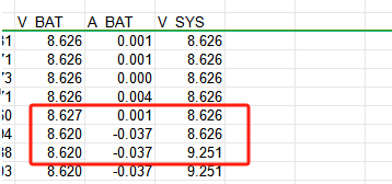
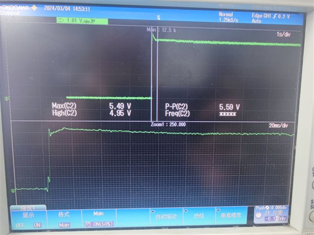
1. Leakage current 1mA waveform after charging:

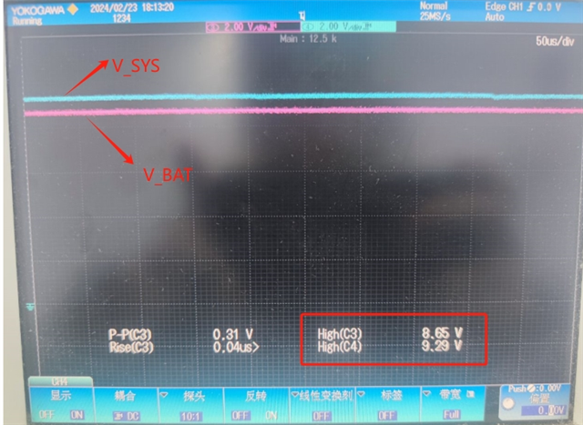
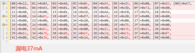
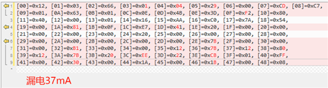
2. The leakage current is 38mA after charging is terminated. When measured, the battery voltage and SYS voltage are similar to the picture above, which are also 0.6V higher.

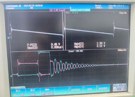
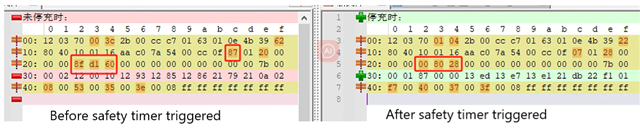
The abnormal waveforms of sw1 and sw2 are as follows:

Please help check it.

Thanks

Star

  • Hi Star,

    Unfortunately, both items are normal operation.  If V(BAT)>VBUS after charge as terminated or charge is disabled, the IC pulls up to 1.7mA from BAT to power the IC.  Regarding the 38mA, if the charger thinks that the battery is OVP (i.e. V(BATP)>VREG*1.03min, it automatically pulls ~35mA from BAT to discharge it.  You may be able to disable the 35mA using REG0x0F[7].

    Regards,

    Jeff

  • Hi Jeff

    Thanks for your reply.

    Application conditions: 2cells battery, maximum battery charging voltage 8.7V, adapter output 5V-2A 

    Charging IC register configuration when starting charging:
    
    OVP function is turned off
    
    Watchdog function is turned off
    
    Charging cut-off current setting 40mA
    
    Charge_Voltage_Limit = 8.7V
    
    Charge_Current_Limit = 2600mA
    
    Input_Voltage_Limit = 4600mV
    
    Input_Current_Limit = 2400mA
    The schematic as below:

    The system was in working condition during the test. The two phenomena occurred at different times on the same board and the same adapter. The test conditions were the same and both were charged with a 5V/2A adapter.

    Due to the limitations of the test conditions (there is only one test instrument and the test cycle is relatively time-consuming), a total of 8 tests were conducted. Only one motherboard measured a discharge current of 1mA after charging was stopped in the first two tests. The subsequent test results were different from other tests. The motherboard results are all 38mA, and the register changes and waveforms are described as below:

    Phenomenon 1: When the battery is fully charged and the adapter is plugged in, there is a leakage current of 1mA, the charging voltage is 8.7V, the cut-off current is 36mA, and the SYS voltage jumps from 8.7V to 9.3V after charging is stopped.

    Phenomenon 2: The battery continues to be charged until the current slowly drops to 1mA, and charging is stopped until the charging time reaches 12 hours. After the charging is stopped, there is a leakage current of 37mA on the battery end with the adapter plugged in. The battery voltage is measured to be 8.62V. After the charging is stopped, the SYS voltage drops from 8.62V. jumps to 9.25V.

    The difference in the register dump results in the two cases is compared as follows:
    Difference 1: Register [03_04] difference, modified after software logic judgment, can be ignored;
    Difference 2: Register [05] Input_Voltage_Limit, the register value of phenomenon 1 (leakage 1mA) is 0x2b (4300mV), the value of phenomenon 2 (leakage 37mA) is 0x29 (4100mA). The software will not modify the register value after setting 0x2e (4600mA). Why does the register value change?
    Difference 3: Register [0F], the register value of phenomenon 1 (leakage 1mA) is 0xb2 (bit6 is 0), the value of phenomenon 2 (leakage 37mA) is 0xf2 (bit6 is 1), the default configuration value of register [0F] is 0x22, What is the reason that triggers bit6:7 and bit4 to be set to 1? EN_ICO is set to 0.

    The battery has been discharged to 8.5V due to leakage. Try setting bit6 to 0 and then recharging the IC. After the battery is fully charged, the leakage is measured to be 1mA. Can this temporary verification result provide some troubleshooting directions to solve this problem?
    Difference 4: Register [19_1A] ICO_Current_Limit, the register value of phenomenon 1 (leakage 1mA) is 0xC8 (2020mA), the value of phenomenon 2 (leakage 37mA) is 0x81 (1290mA);
    Difference 5: Register [1D] Charger_Status_2, the register value of phenomenon 1 (leakage 1mA) is 0x81 (bit6:7 = 2h), the value of phenomenon 2 (leakage 37mA) is 0x41 (bit6:7 = 1h);
    The SW waveform measured by the two phenomena is as follows.
    Is the waveform normal?
    The mass production plan of this project has been suspended due to this fault. Please help to solve this issue.
    Thanks
    Star

  • Hi Star,

    As I mentioned previously, both currents are not unexpected.  When V(BAT)>VBUS>UVLO and charge is terminated or disabled, battery current~=1-2mA is used to power to the converter. The charger was designed with the expectation that input power is removed when charge is complete.  With power still attached, the only issue is that the battery will recharge more frequently.

    Regarding the 37mA discharge current, that is a protection feature for when the battery regulation voltage exceeds VREG setting.  Essentially, with VBUS powered and V(BAT)>VREG after charge termination or disabled, the charger's VBATOVP is lowered to VREG.  Th 37mA is used to discharge the battery down to VREG and cannot be disabled.  Disabling PFM mode might help to prevent battery overcharge.

    Regards,

    Jeff

  • Dear Jeff,

    you referred that " Regarding the 38mA, if the charger thinks that the battery is OVP (i.e. V(BATP)>VREG*1.03min, it automatically pulls ~35mA from BAT to discharge it.  You may be able to disable the 35mA using REG0x0F[7].", "Disabling PFM mode might help to prevent battery overcharge", but i am still a bit confused , would you please help to guide for the below items:

    1. the customer disabled the BAT discharging originally, could the BQ25792 set EN_AUTO_IBATDIS/FORCE_IBATDIS bit to 1 when the BAT OVP fault happens? the original setting of reg 0F is 22h. 

    2. from the tracking data, the BAT voltage is not larger than VREG*1.03 averagely, even if it is triggered by a pulse over voltage, will the 35mA discharging current will be stopped when the VBAT voltage fall in the normal scope?

    3. in addition to setting register 0x12 bit4 to 1, do other configurations need to be configured to disable PFM mode? Disabling PFM mode. Under what circumstances does it need to be disabled? Can the PFM mode be disabled during power-on initialization so that PFM remains in the PFM disabled state? Is this feasible? What impact will it have on charging?

    besides the above issues that Star shared, the customer also found the below issues:

    1. BQ25792 mostly could not stop charging normally, the charging will be terminated by the Fast charge safety timer protection rather than normal termination condition (vbat/charging current), why this issue will happen?

    2. VINDPM will be changed to 4100mV while the customer set it to 4300mV and the ICO_Current_Limit will be changed to 1290mA while the customer set value is 2020mA  originally, the customer also disabled EN_ICO, but BQ25792 enabled it by itself,  why could this issue happened?  the customer AGND is not separated from power GND correctly, will it be related to the issue? will the adapter voltage at the plug-in affect the VINDPM value and EN_ICO/ICO_Current_Limit bit?

    thanks a lot!

  • Hi Andrew,

    Regarding 1 and 2, when charge is terminated or disabled, the VBATOVP is lowered to slightly above VBATREG, not 103%*BATREG.  The auto discharge bit does not turn off this 35mA discharge current.  That bit only disables the 35mA discharge when VBAT>103%BATREG.  Adding more capacitance on BAT (>47uF after derating for applied voltage if ceramic) and disabling PFM help stabilize BAT voltage and prevent this.

    Regarding 3, PFM can be disabled at power up.  It only improves efficiency at ISYS and IBAT << 50mA.

    Regarding 1, battery charge time can be estimated as battery capacity/charge current*1.3 to account for taper.  The taper time is due to additional resistance (copper pour, protector FET, connector, gauge RSNS) between the BATP sense point and the battery pack cells.  Connecting BATP pin as close to battery pack+ helps.  If system load current + battery current requires more input power than the charger can provide due to IINDPM or VINDPM limiting input power, charge is reduced.  If the IC gets too hot, the charge current is reduced by thermal regulation loop.  Do the status and fault register report VINDPM, IINDPM or thermal regulation?  If TS WARM or COOL occurs, charge current can be reduced.  Do the status and fault registers report this?

    Regarding 2, the charger does not auto enable ICO by auto setting EN_ICO=1.  Input current limit is enabled at all times. If ICO is triggering, then input power is not high enough for ISYS+IBAT so IBAT is being reduced. Adapter voltage at plug in before converter starts is used to determine VINDPM value (e.g. 700mV less than VBUS= 5V).  AGND for the Rs and Cs on the TS and VACx pins makes those measurements more accurate but is not required.

    Did the customer follow the recommended layout from the datasheet and EVM below?  If not, charge current can be limited due to noise coupling.

    Regards,

    Jeff

  • Hi Jeff

    Thanks for your help.

    The customer provided the information as below:

    The capacitance of BAT is greater than 47uF, and the TS pin is connected to a 10k resistor to ground. Will the internal thermal adjustment still be effective?

    The fault register reporting values ​​are all 0, Register 0x1B has a value of 0x0F, and no VINDPM, IINDPM or thermal regulation is reported.

    As shown in the following picture, VBUS waveform at the moment of plugging in the adapter, See if it helps to analyze the problem?

    Register 0x0F bit6 bit7 will be automatically set to 1 if OVP occurs, bit4 (EN_ICO) will also be automatically set to 1, is it normal?

    Waiting for your reply.

    Thanks

    Star

  • Hi Star,

    Ceramic capacitors derate in capacitance with applied voltage.  It is unlikely that the total capacitance on BAT is 47uF unless there are more than 10 10uF cermaic capacitors on BAT.  With 10kohm resistance on TS and the recommended resistor divider for 10kohm thermistor, TS function is effectively disabled.  Register 0x0F[7] does not auto set but is 1 by default.  Register 0x0F[6][ may autoset after termination but will auto clear when OVP condition is removed.  I will confirm that with design.  ICO enable bit is 0 but default, does not auto enable and must be turned on by host write.

    What do the charge status bits in REG0x1C[7:5] report?  Taper or termination?  I would expect termination, then 35mA discharge, then taper and repeat.

    Regards,

    Jeff

  • Hi Jeff

    To increase the capacitance, do we need to increase the capacitance of mark point 1 or mark point 2, or are these two positions actually short-circuited, and the capacitance values ​​of the two mark point positions are the same?

    If we need to add 10 10uF capacitors, can we directly connect a 100uF capacitor to replace it?

    The TS pin is not connected to the NTC resistor to ground, but is connected to a 10K fixed resistor. Then the TS function is disabled, and the register 0x0F[7/6/4] will be automatically set. The software does not set it to 1, and the reason for setting it to 1 is unknown. When REG0x1C[7:5] is set to 1, it is a taper. When entering the terminate state, the 35mA discharge will continue. The 35mA discharge will stop only after manually setting 0x​​0F[6] to 0.

    The charging voltage is set to 8.7V. Occasionally, charging stops when the actual charging voltage is less than 8.7V. What could be the reason?

    Phenomenon 1: 8.61V 24mA triggers and stops charging;

    Phenomenon 2: The charging current slowly decreases until the battery experiences dynamic charging and discharging current.

    Waiting for your reply.

    Thanks

    Star

  • Hi Star,

    Increasing capacitance closer to BATP so point 2 would be best because that is the sense point CV loop error amplifier and BATOVP comparator.

    Regarding ICO, there is no relationship between TS disable and ICO enable or BATOVP pull down bits.  I have looked at this on the bench but I will check again tomorrow.

    The 35mA discharge occurs after termination if VBUS is still applied and charge has terminated or disabled AND BATP voltage rises even a few mV above VREG setting as measured at BATP pin. Could it be your battery relaxing to a higher voltage after charge?  It is my understanding that batteries relax to a slightly lower voltage after charge.

    Regarding Phenomenon 1, is the BATP to GND pin measuring 8.61V?  That is the node to which the charger regulates.  We only spec accuracy for VREG = 8.4V as shown below:

     .

    It possible that the regulation gets worse at 8.7V be should not be worse than -0.85%.

    Regarding Phenomenon 2, I do not understand the comment. The charge current should taper down to ITERM setting.  If the SYS load requires more current, the battery will supplement.

    Can you repeat some of these tests on the EVM?  

    Regards,

    Jeff

  • dear Jeff,

    regarding to the Phenomenon 2,  according to the log data as below: the charging current keep at 1mA and the BAT voltage is 8.626V,so i think the charging did not terminate might because the BAT voltage did not reach terminate voltage.

    as the safety timer expire after 12 hours charging, so i think there might be input current/voltage or thermal regulation happens, as the datasheet says below:

    During input voltage, current or thermal regulation, the safety timer counts at half-clock rate as the actual charge
    current is likely to be below the register setting. For example, if the charger is in input current regulation
    (IINDPM_STAT = 1) throughout the whole charging cycle, and the safety timer is set to 5 hours, then the timer
    will expire in 10 hours.

    in addition, i am not sure if the noise at VBAT sensing would affect the charging termination detection?

    thanks!

  • dear Jeff,

    i remember that there is also the ICO issue " ICO_Current_Limit will be changed to 1290mA", i am afraid the charging might already been pended as the input current is limited, the 1mA reported current might be measurement tolerance, is it possible?

    thanks!

  • dear Jeff,

    in addition, you referred "The 35mA discharge occurs after termination if VBUS is still applied and charge has terminated or disabled AND BATP voltage rises even a few mV above VREG setting as measured at BATP pin, Could it be your battery relaxing to a higher voltage after charge?", the battery voltage could not rise up during relaxing. so i am afraid the noise or measurement tolerance might be the reason. by the way, when the 35 mA discharge started, when will it be stopped? will the device stop it automatically?

    thanks a lot!

  • dear Jeff,

    regarding to the Phenomenon 2, the VINDPM reported as 4.01V and the ICO limit current changed to 1.29A after the safety timer triggered as the below picture, I have asked the customer to double check the adapter (change to a power source or redo the VINDPM check) and the registers data before the safety timer to be triggered.

    thanks!

  • dear Jeff,

    the below are the register data before & after the safety timer trigger in Phenomenon 2:

  • dear Jeff,

    the below is the register data when normal charging:

  • Hi Andrew, 

    I don't see safety timer expiration 3 posts above but I do see charge termination, even though V(BAT)=8.4xV with VREG=8.7V.  With VRCH = 200mV, recharge should have started.  Is /CE pin pulled high for some reason?

    The 37mA is due to  
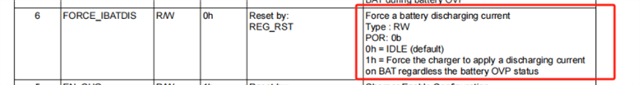
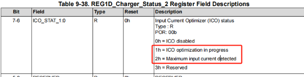
.  Why is that turned on?

    Regards,

    Jeff

  • Hi Andrew,

    From 3 posts above and on the left (before timer expire), I see taper charge but V(SYS)<VBAT as shown below.  The should only happen if the charger is in DPM (supplement) but no DPM is being reported.  That is odd.

    Also  is on.  Why?  I do not recommend this.

    For 3 posts above and on the right side (after timer expire), I see timer expired and not charging.

    Also   is on.  Why?  I do not recommend this.

    Regards,

    Jeff

  • Hi Jeff,

    " Is /CE pin pulled high for some reason?"  The CE pin is grounded by the pull-down resistance and does not have a pull-up operation.

      is automatically set to 1 by the IC, software is set to 0 only during initialization, and the bit will not be set later

  • Hi Guisen,

    Force IBAT discharge is not auto set by the IC.

    Regards,

    Jeff

  • Hi Jeff,

    According to the latest verification results, after removing the operation that set CHG_EN to 1 and HIZ_EN to 0 periodically during the charging process,

    no abnormal phenomena such as triggering OVP were detected during the charging process, and the charging result looked normal.

    It is suspected that this operation caused the abnormal phenomenon, can you explain the reason?

  • CHG_EN is set to 1 and HIZ_EN to 0 every 10 seconds during charging

  • dear Lin,

    what is the battery voltage and charging current/adapter current? are any of the register turned to abnormal?

    please capture the battery voltage/adapter voltage/charging current/adapter current & registers data of different states of EN_CHG & EN_HIZ. better you may log all he register data as well. to avoid the system SW affect, could you stop the SW who may write the registers after the charger being booted.

    thanks!

  • Hi Andrew,

    The charger does not auto change CHG_EN bit.  But it can auto set HIZ_EN=1 if it detects an overcurrent fault but it will not auto set HIZ_EN back to 0 unless there is a complete POR event (both VBUS and VBAT go below there respective UVLO thresholds).

    Regards,

    Jeff

  • Hi Jeff,

    According to the latest verification results, after removing the operation that set CHG_EN to 1 and HIZ_EN to 0 every 10 seconds  during the charging process,no abnormal phenomena such as triggering OVP were detected during the charging process, and the charging result looked normal.

    It is suspected that this operation caused the abnormal phenomenon, can you explain the reason?

  • Hi Andrew,

    "to avoid the system SW affect, could you stop the SW who may write the registers after the charger being booted."
    This experiment has been done before, but the results were also abnormal,probably because the IC had entered an abnormal state before the software disconnected the communication with the IC.

  • Hi all,

    I just realized I posted something incorrect above.  The BQ25798 can set HIZ_EN=1 if poor source detect fails.  Poor source pulls a small current from the input at adapter/port plug. If the VBUS voltage falls below the auto VINDPM register setting, the charger thinks the input source is bad and reports poor source flag.  After ~10min, the charger sets HIZ_EN=1 and tests again.  Could this be an issue?

    Regards,

    Jeff

  • Also, BQ25792 enters HiZ at poor source and stays there until the host writes EN_HIZ bit = 0.

    Regards,

    Jeff