Other Parts Discussed in Thread: LM5060
Hi TI,
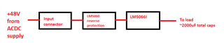
Below is a block diagram of my design. The input power is +48V from an AC-DC power supply, which is connected to the input connector on my board. I have a reverse voltage protection using LM5060 with IPB017N10N5LF mosfet followed by the LM5066I eFuse with IPB017N10N5LF mosfet. The UVLO/EN is set to be 39V by using a resistor divider to Vin. The eFuse output is connected to the onboard circuitries with total load capacitance of around 2000uF. I do not have any bleed resistor to GND to discharge the eFuse output
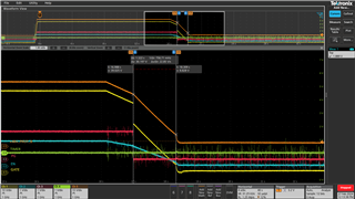
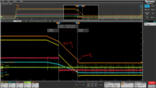
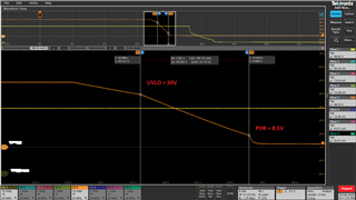
I am observing the following discharge waveform when +48V from the AC-DC is unplugged from the input connector. This is to simulate a user condition when the AC-DC is accidently disconnected from the input connector. From the scope shot, the output voltage ramps down to UVLO threshold of 39V and ramping down faster until it hit the POR of about 8.8V (1.34s from UVLO to POR threshold) and finally discharge further exponentially. Without any bleed resistor to GND, I am expecting the discharge for 2000uF to be close to 100s. However, the discharge observed from measurement shows that the discharge time is less than 2s.
Can you share the internal behaviors of the IC for the above turn off condition?
Is there any discharge path internal to the IC that will discharge the output once UVLO is reached?
Refer to the orange line for the voltage at OUT of LM5066I and please ignore the yellow line
Thanks