This thread has been locked.

If you have a related question, please click the "Ask a related question" button in the top right corner. The newly created question will be automatically linked to this question.

TPS62813-Q1: Device hiccuping and getting hot

Part Number: TPS62813-Q1
Other Parts Discussed in Thread: TPS62813

Hi all,

(First post/question)

This is regarding a TPS628132MQWRWYRQ1, fixed 1.8V regulator.

I have the following circuit to generate a 1.8V rail, and upon applying 5V on the input, it starts up and then enters a noisy hiccup scenario, which never ends. It is also getting very hot on the board (>70C) so it's dissipating a lot of energy. I don't leave it on long.

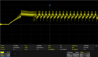
Here are some plots of the output, it averages about 1.5V:

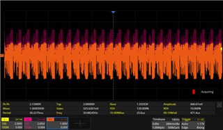
Here is the voltage across the inductor (C1 and C2 are voltages either side, with the orange plot being C1-C2):

I've tried everything I can think of:

  • Verified that resistance checks across all pins to ensure no shorts
  • Output resistance ~= 300Ohm
  • Injected 1.8V on the output (without 5V on), and measured <0.4A which is much under the rated 3A
  • Increased the soft start time to ~200ms (shown in the first plot above) to mitigate effects of excessive capacitance on the 1V8 rail (by other circuits on the board) causing it to go into overcurrent shutdown during startup
  • Verified that the 5V0 rail is not drooping or anything upon startup
  • Changed the compensation resistor to GND as well as 5V0 rail, to see if that has any effect and I can see the difference in hiccup frequency but otherwise it still does it

I have 2 boards made, and they both exhibit this behaviour so it doesn't seem to be a manufacturing fault.

I'm using this design on a separate board and it works fine.

What could be leading to this behaviour?  Would appreciate any ideas.

Thanks!

  • Hello Corey,

    To undersdtand it more:

    • What is indcutor P/N and value you are using? What is the saturation current of inductor?
    • What is the load you are using? You said 330 ohm reistance. So Iout =V/R=6mA. Is that right?
    • Can you measure the Vout, SW node voltage and Inductor current with smaller time division on oscilloscope so that I can see what really is happening?
    • Is this 5V0 VIn is coming from some othe rmodule or it is from the power supply?
    • Is the output connected to some other rail?

    When you say this: "I'm using this design on a separate board and it works fine"  So you have the same BOM and IC on separate board. What is the different between thos two first boards vs the another board design which is working fine?

    Thanks,

    Farheen

  • Hi Farheen,

    Thanks for your quick response.

    - The inductor is a Wurth 744383340056. It is rated at 5.8A, saturation current is just over that.

    - The load (as measured when I injected 1.8V from an external source) is about 400mA.

    - I may be able to get a higher resolution image tomorrow (I'm in Australia, it's evening here now). There is a lot of switching noise, could that be contributing?

    - The 5V0 is coming from another module, it looks to be well regulated and has a low ripple.

    - The 1.8V output reticulates to a number of loads with their own bypass capacitors. Could the issue be too much capacitance?

    Your statement about the other board is correct. I have this exact circuit (as shown in the schematic above) on another board, supplying a number of loads on the board and it operates as normal. The difference between the boards is a clock generator and a couple of clock multiplexers (which have ferrite bead pi-filters to mitigate noise transmission up the chain).

    Hope that helps.

    Thanks,

    Corey

  • Hello Corey,

    Thank you for your quick response. It can be because of high capacitances also. That is why I want to have a look at inductor current because that will help me to understand  what is happening with the device. HICCUP is normally triggered by OCP and increased capacitance can trigger the OCP. During startup, higher current will be needed to charge this higher output caps when output voltage rises (According I=C*dv/dt)

    Also because of the noise I can completely understand the cycle.Is the first measurement of Vout the start up behavior?

    Thanks,

    Farheen

  • Thanks Farheen. Yes, the first plot shows the Vout as the soft start picks up and begins the hiccuping behaviour. And the 2nd plot shows (in orange) the voltage across the inductor terminals. The DC resistance is 29mOhm. I will see if I can get a slower plot today if it helps.

    Noting the capacitance potential issue, I tried slowing down the SS startup time considerably (from <1ms to 200ms), maybe I'll try to increase this more. I thought this would allow for charging of the caps and avoid OCP.

    At this point I don't know if it is noise or capacitance causing the hiccup. The noise (which looks like switching noise to me) is emitted by the  TPS62813, which makes me think it needs more capacitance? The first plot above shows the solid yellow line which is pulsed DC, and the "fluff" above and below it is what I think is switching noise. You can see it increase as the voltage increases. I don't think there is a great deal of capacitance on the Vout (1.8V) rail, it must be only a few hundred uF and as for PCB plane capacitance, it's not a plane, more just small patches and traces.

    Thanks,

    Corey

  • Hello Corey,

    It is lot of noise. Have you tried to reduce the bandwidth of the oscilloscope to avoid the unrelated noise. how you are measuring it? Sometimes probing approach helps also. I recommend to use tip and barrel technique.

    To have zoom in Vout and inductor current curve can give more insight. We can observe cycle by cycle and see that is the inductor current hitting the limit or not.

    Is there a way to disconnect the rest of circuit at output and just monitor the output voltage, inductor current and switching frequency without them? Because that we can rule out the option of external capacitance. 

    Thanks,

    Farheen

  • Hi Farheen,

    I found the issue, after trying just about everything I could think of. It turns out the inductor was mounted 90-degrees from how it should have and was shorting the inductor pads on the board. So effectively the TPS62813 had no external inductor. Re-seating it correctly using a heatgun fixed the issue completely and it works well now, in the original configuration as shown in the schematic above.

    In trying to get to the bottom of the issue, I had cut tracks to remove all loads, removed a lot of capacitors, adjusted the compensation to various levels, decreased the startup, etc, etc - and all to no avail - of course until I tried removing and downsizing the inductor and noticed the pads were perpendicular!

    Thanks for your help.