This thread has been locked.

If you have a related question, please click the "Ask a related question" button in the top right corner. The newly created question will be automatically linked to this question.

BQ51050B: charging current

Part Number: BQ51050B

Hi All,

I have a question about the BQ51050B.

I am using BQ51050B to charge lithium battery 2000mA battery. 

I know max charging current of BQ51050B is 1.5A. and I want to charge the battery at 1.2A.

So, I set below.

R1 : 62ohm

RFOD : 200 ohm

RILIM : 262 ohm

Ibulk = 314 / 262 = 1.2 A

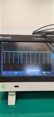
However, when I measured the battery charging current, it was measured at 800mA.

Charging current is moved from 800mA to 0A. is it ok?
And how can I make it charge at 1.2A?

Additionally, I confirmed that wireless TX IC transmits at 9V 900mA, and TX coil inductance is 9uH, RX coil inductance is 8 uH.

Refer to below schematic 


  • Hello

    Schematic looks OK, nothing is point to a problem.

    The Scope capture of output current could be better.  During communication time the current is dropping to 0mA.  Rate is 250ms this is about right, if you see 30ms this indicates a problem. Need to see what RECT is doing.

    A couple of things to look at:

    1.) Which RX coil are you using, is a datasheet online?

    2.) Can you share a scope capture of RECT under 800mA load?

    3.) Which Transmitter are you using in your test?  Any indications it is at max output power?

  • Hello. Thank you for cooperation.

    I checked below things.

    1.) Which RX coil are you using, is a datasheet online?

    => I use customized coil.

    Sample

    Inductance(uH, +/- 10%)

    R(@100kHz,Ω)

    DCR(Ω)

    Q(@100kHz)

    Min

    Normal

    Max

    TX

    8.1

    9

    9.9

    0.072

    0.077

    78.54

    RX

    7.2

    8

    8.8

    0.368

    0.345

    13.66


    2.) Can you share a scope capture of RECT under 800mA load?

    => I captured RECT pin and BAT current.

         Refer to below image.  (CH1 : RECT    / CH2 : BAT CURRENT)


         Transmitter IC transmit as 9V.(Refer to below image). but RECT voltage level is max 6V. is it ok?


                                           < TX IC>

    3.) Which Transmitter are you using in your test?  Any indications it is at max output power?

    => I use CPS8601 as transmitter. CPS8601 support WPC 1.3 EPP 15W.

    Thanks a lot.

  • Hello

    I suspect the drop in current is due the Adaptive Communication Limit feature (see datasheet section 8.3.4.9). The current will be limited to 400mA during this time.  Depending on the battery behavior the charge current could go to 0mA.

    As a test try reducing the charge current below 400mA, if it is the limit feature the drop out will stop.

  • Hello.

    Sorry. I have a mistake.

    I don't consider Board power consumption.

    I disconnect main board and charger block.

    So charging current is 1.2A.

    During communication time the current is dropping to 400mA. is it ok?

    I have a question.

    Recommended input voltage range is 4V~10V. so can't we transmit 12V?

    Thanks a lot.

  • During communication time the current is dropping to 400mA. is it ok?

    Yes this is normal operation for the unit.

    Recommended input voltage range is 4V~10V. so can't we transmit 12V?

    4V to 10V is the voltage at RECT pin, this is full wave rectified AC voltage.  The BQ51050B will adjust the RECT voltage as needed to charge battery by sending commands to the TX.  BUT all internal and you do not have control of the voltage. 

  • Hello.

    Thanks a lot.

    I have one more question.

    Can I control communication time? 

    For example, Can I change 250ms to 1s? 

    Or, Can I remove communication time?

  • Sorry but the timing is internal and cannot be changed.