This thread has been locked.

If you have a related question, please click the "Ask a related question" button in the top right corner. The newly created question will be automatically linked to this question.

TPS65131 Problems

Other Parts Discussed in Thread: TPS65131
  • Sorry something did not work, my post:

    Hi, I use the TPS65131 to bias an OLED Display with +/-5VDC.

    The chip is working excellent so far, but now I have a few Boards (approx. 3 out of 100) which show a huge Ripple on the VDD +5V even without any load!

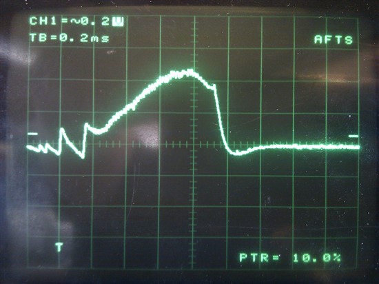
    The Ripple is a sawtooth waveform with a steep up-ramp and about 30mS! down-ramp. The ripple is about 200mV!

    The absolute (effective) Voltage Value is 5.07V which would be in the correct Range.

    I have checked all the Passive components and already replaced all of them!

    btw. The negative Voltage is perfekt.

    Is there a Problem inside the chip? Or what could cause such a Ripple?

    It's almost impossible for me to desolder this chip!

  • Is power save mode enabled?  Does the ripple go away if you disable power save mode? What is the input voltage and load current when you see the ripple?

  • When I disable the powersave mode on the psp pin, the ripple changes to a much higher Frequency (1,2 ms period).

    The ripple is even higher at about 300 to 400mV.

    My input Voltage is a nice 3,3V. The ripple is present with no load as well as with the display connected (dynamic load OLED).

    The look of it's waveform changes a littlebit when loaded, but not really much.

  • This is the waveform I have without any load.
    Now with power save disabled.
    If enabled the spike is the same but the voltage drops slowly until the next upspike in 30ms.

    It repeats every 30 to 35 ms!

    This is my schematic, which does a very good job with 15mV ripple in most cases (98% of all pcbs):


  • Hello Markus,

    Is it possible that the IC is not perfectly soldered and has some issues on FBP which causes this strange behavior?

    Please check the connection to the CP capacitor and the CP voltage. Does this relate to the output voltage somehow?

    Is there a possibility to take a good board and replace all external components of the boost converter with the ones from the good board and check if at some point the good board gets bad or the bad board gets good.

    Please check the INP pin throughout this test, as well as the output voltage and if possible the CP capacitor.

    If this does not change the behavior of the boards take the unit from the good board and solder it to the bad board and vice versa and check if the problem is moving with the part.

    Best regards,
    Brigitte