This thread has been locked.

If you have a related question, please click the "Ask a related question" button in the top right corner. The newly created question will be automatically linked to this question.

UCC23514: Abnormal waveform issues of chips

Part Number: UCC23514

Miller clamp seems to be ineffective, there is an abnormal waveform issue with the chip.

U200 and U201 are both the same situation

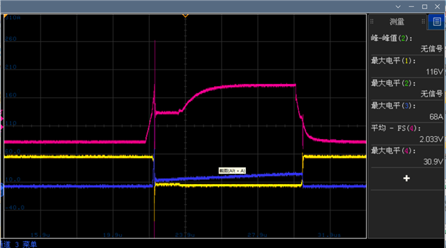
The red waveform represents the driver, the yellow waveform represents the VDS, and the blue waveform represents the ID current.

7457.Schematic Prints.pdf

  • Hi Tony,

    The UCC23514 has an internal clamp. You are trying to use it to drive an external clamp. The internal clamp must sense a gate voltage below 2V after the falling edge of OUT before it will turn on. In your circuit, it may be able to sense this through the 100 ohm RD200,1,2,3. But I'm not sure. 

    You should never put resistance in series with a Miller clamp. It appears R401, R399, R400, and R398 are 10 ohm resistors in series with an external Miller PNP device. Does the issue persist if these resistors are exchanged for a 0 ohm value?

    Best regards,

    Sean

  • Your method did not solve the problem. Please help to see if there are any other issues and provide a solution. Thank you!

  • Apologies Tony,

    Is this red waveform BOOST or BUCK_DRV? Do you have a waveform for both? The Miller clamp is designed hold off an undriven FET. It will only sink current if OUT is <2V. In your waveform, the ID spike occurs when the OUT is high. 

    When you close a switch that has a high voltage across it, the Miller capacitor extracts transient current, as the Cds voltage collapses quickly. What you claim to see here is a charge injection. 

    Is this possibly the reverse recovery current of the body diode of a high-side STGW60H65DFB? If so, you can increase efficiency by slowing the Vds edge rate. Also, adding some trace length to the drain of the IGBT will add series inductance, and can help absorb some dV/dt at very high frequency.

    Alternatively, you could use a switch with lower reverse recovery current.

    Best regards,

    Sean