This thread has been locked.

If you have a related question, please click the "Ask a related question" button in the top right corner. The newly created question will be automatically linked to this question.

BQ25750EVM: Switch time from VIN to Battery for VSYS Power

Part Number: BQ25750EVM
Other Parts Discussed in Thread: BQ25750, BQSTUDIO

Hello Expert,

We are evaluating BQ25750EVM.

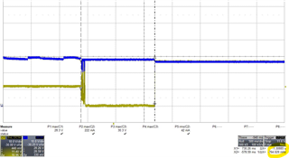
The switching time from VIN to the Battery for VSYS power is measured to be approximately 1.3 sec.

Here is waveform.
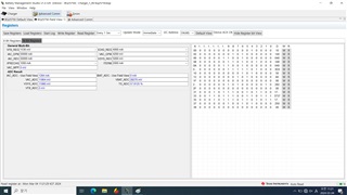
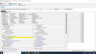
Captured of Battery management Studio
When VIN power is cut off, how long does it take for Battery power to be connected to VSYS?

What's the best way to reduce switch time as much as possible?

Best Regards,

Michael

  • Looking at the Studio screenshot, it says not charging and not power good. Just confirming that is because there is no VIN when this capture was taken ?

    In our experiments, we have noticed that the ACDRV takes 3ms while the VSYS takes less than 1ms to switch after handover. The 1.3s number does not seem right.

  • Hello Expert.

    When VIN is disconnected and switching from VOUT/VBAT to VSYS through BAT_DRV there is a delay time of approximately 1.3 seconds.

    When using the AUTO REV_function, a delay of approximately 3ms was confirmed.

    We would like to use the BAT_DRV function.

    I would like to know how to switch without delay using BAT_DRV.

    VIN: 9~36VDC
    VBAT: 28VDC

  • Hi,

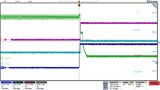
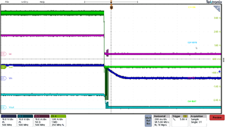
    The AUTO_REV function is for the reverse mode operation of the device. It does not control the power path transfer. The ACDRV and BATDRV timings should be very similar and waveforms should be opposite. In our tests, we have seen power path transfer happen in a few miliseconds. I believe maybe there is a problem with the setup or we are missing something here if you see 1.3s. Could you please plot IBAT, ACDRV, VSYS and BATDRV on the scope for both VAC--> VBAT and VBAT--> VAC transfer and share with us ? For the same VIN and VOUT voltages. Furthermore, do you have a load ?

  • Hi,
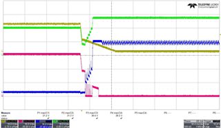
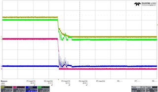
    I am attaching the waveform you requested.
    It operates normally at 0A, but does not operate at over 0.5A.

    # Could you please give me the demo board you have?

    CH1(YELLOW):VAC
    CH2(RED):ACDRV
    CH3(BLUE): BATDRV
    CH4(GREEN): VSYS

    <0A LOAD>

    <0.5A LOAD>

    bq25750_0307.txt
    * Created: Thu Mar 07 10:15:28 KST 2024
    *
    * Format: Register Name  tab Character,\t  Register Address  tab Character,\t  Hexadecimal register value.
    * BQZ Container: Charger_1_00-bq25750.bqz
    *
    Charge Voltage Limit	00	10
    Charge Current Limit	02	140
    Input Current DPM Limit	06	640
    Input Voltage DPM Limit	08	348
    Reverse Mode Input Current Limit	0A	640
    Reverse Mode System Voltage Limit	0C	1C20
    Precharge Current Limit	10	50
    Termination Current Limit	12	A0
    Precharge and Termination Control	14	0F
    Timer Control	15	4D
    Three-Stage Charge Control	16	00
    Charger Control	17	C9
    Pin Control	18	C0
    Power Path and Reverse Mode Control	19	00
    MPPT Control	1A	20
    TS Charging Threshold Control	1B	96
    TS Charging Region Behavior Control	1C	57
    TS Reverse Mode Threshold Control	1D	40
    Reverse Undervoltage Control	1E	00
    VAC Max Power Point Detected	1F	00
    Charger Status 1	21	06
    Charger Status 2	22	80
    Charger Status 3	23	02
    Fault Status	24	00
    Charger Flag 1	25	00
    Charger Flag 2	26	00
    Fault Flag	27	00
    Charger Mask 1	28	00
    Charger Mask 2	29	00
    Fault Mask	2A	00
    ADC Control	2B	60
    ADC Channel Control	2C	0A
    IAC ADC - Use Field View	2D	00
    IBAT ADC - Use Field View	2F	00
    VAC ADC	31	00
    VBAT ADC	33	00
    VSYS ADC	35	00
    TS ADC	37	00
    VFB ADC	39	00
    Gate Driver Strength Control	3B	00
    Gate Driver Dead Time Control	3C	00
    Part Information	3D	02
    GM Adjust	61	30
    Reverse Mode Battery Discharge Current	62	02

  • Looking at your results, I must ask what components are you using ? I feel that they might not be sufficient to handle power path transfer. Are you using the same components as the datasheet available on our website or do you hve your own components on your own board ? Power path transfer is dependent heavily on the SOA of the MOSFETs used and also the supporting inductor, capacitor etc. Please let me know your system specfications including switching frequency as well. Please refer to this link for our datasheet to see the parameters and also order a demo board if needed.

    www.ti.com/.../BQ25750

  • Hi Sung, are you using the default BQ25750 EVM from TI ? That is the same one I am using. My ACFETs and BATFETs are AONS6276.

  • hi,
    We did not change any part of the demo board.
    I would like to request a waveform that switches.

    After completing charging from VAC to VBAT, take a picture of the waveform output to VSYS through BATDRV_FET when VAC is turned off.

    Please provide BQ-Studio registration file.

    VAC_MIN: 9VDC
    VAC_MAX: 36VDC
    VSYS: 5A
    VBAT:LI-ION_7S1P

  • Hi Sung, I will try to recreate the same condition that you have in the lab and get back to you with the waveform next week.

  • hi.
    When can I receive the requested waveform?

  • Hi Yun,

    Thank you for being patient. I am very busy with a lot of work but have procured a board to perform the desired tests. I will try to get you the waveform before the end of this week. Sorry for the delay.

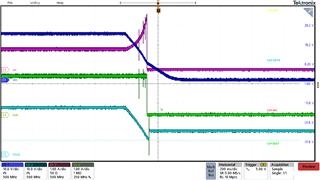
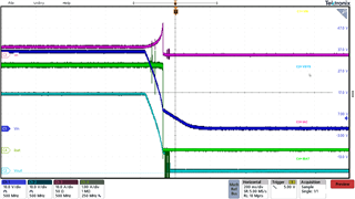
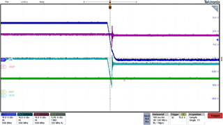
  • Hi Yun, please see attached some basic waveforms. Before I proceed with your specific waveforms, I want to confirm, do you want 5A load or 0.5A load. Earlier you mentioned 0.5A and later 5A so I just wanted to check and make sure.

  • Please see below the specific conditions you requested.

  • HI. Gupta,

    I requested VSYS_5A load.

    If you look at the uploaded waveform, you can see that after VIN is turned off, VSYS is also turned off.
    It has not entered BAT mode.
    I would like to see the voltage output across the BAT DRV_FET after VIN is turned off.

    Please take a picture of the following waveform.

    CH 1 : VIN_28VDC

    CH 2 : VSYS

    CH3 :  VOUT(battery)_24VDC

    CH4 : VSYS_Current_5A

  • Hi, I will get back to you with that waveform this week.

  • Extremely sorry for the delay, I was very busy. Please see above what you requested.

  • hi,
    Thanks for your reply.
    Please provide the "bqStudio Registers" file you tested.

  • I will get back to you on this.

  • Hi, we are using some experimental settings to achieve the results I shared with you. These settings are not final yet and cannot be modified by the user. These settings are set at the factory.