This thread has been locked.

If you have a related question, please click the "Ask a related question" button in the top right corner. The newly created question will be automatically linked to this question.

BQ28Z620: UNABLE TO PROGRAM DATA FLASH for CONFIGURATION

Part Number: BQ28Z620
Other Parts Discussed in Thread: BQSTUDIO

I am trying to configure a BQ28Z620 device on our custom PCB .... although the schematic is pretty much exactly the same as per the device TRM and evaluation module.
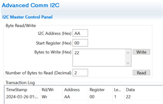
Connection via i2C from a RPi Compute Module 4. 
Code is written in Python 3.

I am able to read and make sense of all the registers so can collect parameters such as battery voltage/current/temperature etc. This all appears to be working as expected.

The problem I am having is writing to the Data Flash so that I configure the device for our purposes.....

I can read back the DF and values are as per default values given in the Tech Ref Manual.
BUT all attempts to write to DF have so far failed to change the data stored within.

I have tried tried various approaches including writing exactly as described in the TRM. Register 0x3E  + block [start address + data] ~ little endian.
I also tried calculating and writing checksum and length into the appropriate places at register 0x60 0x61
Also tried writing everything address/data/csum/length in a single i2C transaction.
Different boards, all virgin, show exactly the same behaviour.

Nothing changes and when I read back the DF data remains as per default values.
[ FYI - I am reading 0x0204 in Control Status register and 0x6100 in Operation Status register ] - There seems to be Multiple SEC bits as shown in the TRM and these are all different ????]

By default my battery is disconnected from the output terminals ..... I have a charging circuit but that is also disconnected from the battery.
Seems that CHG-FET is turned on but DSG-FET is still disabled.
This I think is because the configuration settings are not yet correct.

Questions -- what am I missing with writes to flash ? 
Can the flash memory be write protected in which case how to I disable ?

Happy to share any code and schematics if appropriate !

  • Hello Steve, 

    Can you please provide me with your schematic and with an example of the commands you are writing to the gauge to try and change the DF? I suspect there is an issue with how you are trying to write to the DF since you are seeing this behavior across multiple units. 

    Regards, 

    Jonny. 

  • Hi Jonny.
    I replied to the original message but email has bounced back so I guess you didn't receive that.
    Can you provide me with another email address as I am not sure that it's good to post schematics and code here.

    In Summary however My original attempt at updating the Data Flash was as per the suggestion in the TRM.
    [at Register 0x3E send DF Address followed by data all in little endian format]
    Code looks like this ....

    def write_flash(addr, data):
        wr_data = [(addr & 0x00FF), (addr >> 8)]
        wr_data[2:] = data
        with SMBus(1) as bus:
            bus.write_i2c_block_data(i2Caddr, regAddr, wr_data)

    [ialready defined:  2Caddr = 0x55 //  regAddr = 0x3E]

    This didn't work so I changed the function to also calculate csum and data length ..... which were then written to register 0x60/61
    Final attempt was to always write a FULL data block [32bytes] + checksom + size all in a single i2C transaction.

    Still not working !!

    def mac_write_data(addr, data):
         size = len(data)
         if size > 32:
             print("Data Size must be 32 bytes or less")
             return
         odata = [0] * 37
         # populate data buffer
         odata[1] = addr & 0x00FF
         odata[2] = addr >> 8
         for c, d in enumerate(data):
             odata[c+3] = d
         # calculate checksum
         csum = size
         for d in odata:
             csum += d
         odata[35] = (~csum & 0x000000FF)
         odata[36] = size
         # add the command register address to the front of the buffer
         odata[0] = 0x3E

         print("Flash Data WR: ",end="")
         print_list(odata)

    # necessary to overcome the smbus limitation of 32byte max data length
         with SMBus(1) as bus:
             msg1 = i2c_msg.write(i2Caddr, odata[:32])
             msg2 = i2c_msg.write(i2Caddr, odata[32:])
             bus.i2c_rdwr(msg1, msg2)

  • Note in the above code the data is written in two chunks as smbus has a theoretical maximul data size of 32 bytes. [i2C does not but - smbus is the usual python library]
    I also tried setting msg1 to use the full odata buffer size and writing that as a simple transaction.
    According to my logic analyser there was no difference to the data on the bus and in both cases all data was transferred in a single transaction without repeated stop/start bits etc.

  • Hello Steve, 

    Please send me a friend request so that you can share the schematic over a direct message. 

    Regards, 

    Jonny. 

  • So Jonny. I linked to your friend request and subsequently sent linkls to schemartic and code.
    Haven't heard from you .....
    Now the issue is showing as Resolved which it definitely is not ????

  • Hello Steve, 

    I have taken a look at your schematic and noticed that you are using 100k ohm pull up resistors on the SDA and SCL lines, and these are pulled up to a 5V source. This is not typical, we usually see 10k ohm pull up resistors used and being pulled up to a 3.3V steady source. This difference could be the cause of the trouble you are having, assuming you are attempting to write to the DF correctly. To ensure that you are correctly writing to the DF, I recommend referring to this E2E thread as I believe it is helpful for this case. 

    Regards, 

    Jonny. 

  • Hi Jonny
    Those 100K pullup resistors are not fitted to the board I am working on -- I have the i2C correctly configured with 5K1 pullups to 3.3V.
    As I already statedthe read back from i2C is working just fine so don't suspect any funnies on the bus.

    { FYI the purpose of those extra pullups were because we have one application for this board where there is no MCU available. The idea was that we would program the battery manager in production and then the board should run autonomously. I wasn't sure if there would be a problem leaving the i2C bus dangling so added a position for a resistor just to tie the signals off. } 

    Seems to me the problem is still in the software although I can't see what I am doing wrong ... I am going to try building the code in C which gives me a bit more control over the i2C bus ....... but I have never before had a problem bringing up new projects with python code and it's way quicker to try things out !

    This issue IS NOT resolved ...... why has the Thread been marked as done ????

  • Hello Steve, 

    { FYI the purpose of those extra pullups were because we have one application for this board where there is no MCU available. The idea was that we would program the battery manager in production and then the board should run autonomously. I wasn't sure if there would be a problem leaving the i2C bus dangling so added a position for a resistor just to tie the signals off. } 

    Understood, thanks for the explanation here. 

    In regard to your second comment, you can refer to the Gauge Communication document as I believe it could be helpful here. 

    Regards, 

    Jonny. 

  • Sorry to be a persistent nuisance.
    I finally managed to get the i2C communication running correctly by switching to a different python i2C library.
    Now I am able to read and write correctly to the Data Flash and I have verified that these changes are held through a complete power shutdown.

    Unfortunately though I am still stuck......

    It seems that whatever I do the battery pack is isolated both from the output terminals and the charger.
    Reading back i2C data shows the correct voltage for the battery pack [8.2V] but Zero current flow.
    Looking at the two FETS ....
    The DISCHARGE FET [which is QF1 on my schematic] has 0V on both Gate and Source when no charger voltage is applied.
    When the charger IS powered then I have 8.2V at both G and S 
    I think in both conditions this FET is OFF.
    The CHARGE FET [QF2] is unchanged when charger is switched on/off. 4.1V on the Gate 8.1 ~ 8.2V on the Source.
    DRAIN of both FET's is at around 8.1V always.


    Note I am running with two 18650 batteries connected in Series.
    I have almost fully charged batteries installed at the moment and approx 100mA dummy load [which is only powered when the external source and charger is running]

    I followed the setup details in the data sheet and I have tried poking values into various registers including trying to manually set the state of both FETS to ON but so far I have not found anything which alters the behaviour of the circuit in any way.
    Obviously I am doing something fundamentally wrong but at this point I am completely at a loss.
    Any help or suggestion appreciated.
  • Hello Steve, 

    I am glad to hear that you managed to get the I2C communication operating properly. For the FETs, do you have the FET_EN bit set?

    Regards, 

    Jonny. 

  • So if I use MacSubCmd to read Manufacturing Status at Register 0x0057 value is 0x0000 so apparently the FET's are not enabled.
    {If I set calibration mode then bit15 of this register goes high so I am pretty sure that this is the correct register & data].

    Next question then is how do I set FET_EN bits [and presumably I also need to enable Gauging and Data Collection - same place ??????]

    In the TRM [SLUUC09-DEC 2022] Section 15.3.6 there is a "Manufacturing Status" Register in Data Flash - default set to 0x0000 so I think I need to change this.
    The address of this register is however not evident ...... in the DF table there is a value for "Mfg Status Init" at address 0x43C0 but I can find no exact match for "MANUFACTURER STATUS"..... Changing the value at 0x43C0 does nothing as far as I can tell [ and this is an weird address being a long way from the address range of most of the other settings].

    I also tried using a MACsubCommand to enable and disable FET's [e.g. at Register 0x0022]  but this results in a bus error on the i2C bus.
    Other sub Commands work just fine using same software function so I have no idea yet about this. Will try to debug.

    So still no idea = how do I change FET_EN value and get this part to do something useful ?!?!?

    Have to say that the documentatiuon for this part is terrible. Descriptions are cryptic and there are many errors and ommisions.
    Please help me with more than a one line answer.


  • Hello Steve, 

    To set the FET_EN bit you can write the 0x22 to the start register 0x00 and the I2C address 0xAA. I have tried this with my EVM and bqStudio to confirm. Please see the image below. 

    Regards, 

    Jonny.