This thread has been locked.

If you have a related question, please click the "Ask a related question" button in the top right corner. The newly created question will be automatically linked to this question.

TPS61046: TPS61046YFFR performance Optimization: Measured Efficiency vs. Simulation

Part Number: TPS61046

Hi, 

I am writing to request your assistance in improving the efficiency of a boost converter circuit in our design.

We are currently using the TI TPS61046YFFR to convert a LiPo battery voltage (3.0V to 4.35V) to 10V for powering the OLED display.

Typical load current: 5.5mA at 10V output

Measured efficiency:

67% at 4.22V input voltage

68.5% at 3.85V input voltage


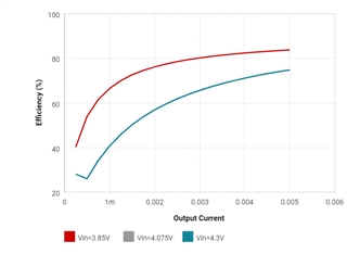
The measured efficiency is lower than in the WEBENCH Power Designer simulation with similar components.

Simulated efficiency:

75% at 4.3V input

83% at 3.85V input

my design

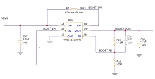
I have limited PCB size and height restrictions for the boost circuit and the output voltage noise below 50mV (critical for noiseless OLED display).


Bill of Materials (BOM):

IC: Texas Instruments TPS61046YFFR

Inductor: Bourns SRN3012TA-100M (10uH, DCR=0.245ohm, Isat=0.76A)

Input Capacitor: Murata GRM033R61A225KE47D (2.2uF, 10V, X5R, 0201)

Output Capacitor: Samsung CL05A475MO5NUN (4.7uF, 16V, X5R, 0402)


We would greatly appreciate your expertise in identifying potential areas for improvement in our boost converter design to achieve the simulation efficiency levels while adhering to the size, height, and noise constraints.

Thank you for your time and support.

  • Hi Kobi,

    I'm in checking and will get the feedback to you asap.

    May I check how do you measure the Vin, Iin, Vout and Iout (the measure point) for the efficiency calculation?

    Regards

    Lei  

  • I have two 0.1 ohm sense resistors connected in series, one with the input voltage and another with the output voltage. I'm using an Agilent 34401A to measure current and voltage.

  • Hi Kobi,

    From the schematic I don't see the concerns that will cause large power loss. The 0.1Ω sense resistors won't cause such a big efficiency gap.

    Here are the two possible reasons.

    1. The additional power loss (around 13.8mW) may be caused by the inductor AC loss
      1. There is no AC loss data on website for the inductor you used. Please try the EVM inductor FDSD0420-H-100M on your board and measure the efficiency again;
    2.  The efficiency gap may be caused by the measuring methods.
      1. Is the 5.5mA lout generated by an E-load?
      2. Is the 5.5mA Iout measured by Agilent 34401A?
      3. Is the input current also measured by Agilent 34401A or Vin supply source?
      4. Is the voltage measured at Vout pin exactly 10V?
      5. Is the Vin measured at the device Vin pin?

    Please help check the above items if you are available.

    Regards

    Lei