This thread has been locked.

If you have a related question, please click the "Ask a related question" button in the top right corner. The newly created question will be automatically linked to this question.

LM5176: Vout drop issue at -35 Deg

Part Number: LM5176

Hi Sir,

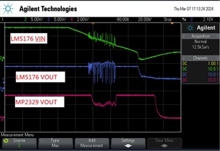
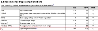
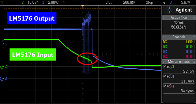
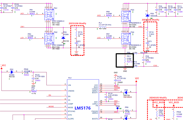
LM5176 Vout will have abnormal problem in low temperature ambient( -35 deg.).

all around component are between -55~150 deg.

currently, the customer design LM5176 is DCIN 12V or 24V ==> LM5176(8.25V) ==> MP2329(3.3V).

may we know that LM5176 can work at TA=-35 deg.?

any idea or suggestion for us? thnaks for you help and learn from you.

  • Hi Tommy,

    thank you for using the E2E forum.

    The LM5176 is specified down to -40 Degree.

    Can you explain why the input voltage for the LM5176 does drop?

    For what input voltage range has the power stage been designed?

    Best regards,

     Stefan

  • Hi Sir,

    Can you explain why the input voltage for the LM5176 does drop?

    [Joe]

    It's the voltage difference caused by the voltage step on the oscilloscope and the use of a diode on the Vin path, as attachment. I try to adjust voltage step 10V to 5V, the voltage is not difference to much. Our input voltage range is 5~36V, during the test, we use the 12V and 24V adaptor for testing.

    During the test, 12V and 24V were used for testing.

    The problem of voltage jitter only happen at low temperatures(-35D) when the adapter(AC side) is removed.

    I tried to do the some testing, it's also happen with other DUT and I found the jitter happen that the voltage mod change buck to boost when remove the adaptor out as show the below.

    12V Adaptor

    24V Adaptor

    LM5176 for vendor.pdf

  • Hi Hung,

    just used the quickstart calculator ( can be found on the product page) 

     LM5176 Design Calculator

    and entered the design data base on the info in the schematic 

    Note: assumed a DC BIAS of the output cap of 50%

    With VIn if 7V the design only has 31 Degree phase margin / with 5V only 13 Degree.

    So the compensation loop might get unstable.

    You might try the design with

    374 Ohm / 33nF / 15nF for PR13 / C963 / PC24

    Please also use the calculator to check your design.

    Note: UVLO is also set to 2.7V which is very low for a design which should work up on 7V.

    Note: Slope compensation value is set higher then recommended. Use the recommended value or the next lower.

    Best regards,

     Stefan

  • Hi Sir,

    We did a lot of testing to look for possible issue. We found the  issue maybe from the PR11(0.004R) as follow the figure black box. We don't see this issue when we use the different vendor, so I want to know if the resistance of current feedback (PR11=0.004R) is maybe cause this issue? Thanks.

  • Hi Hung,

    the current signal of the current sense resistor connected to CS/CSG is an essential part of the control loop for the LM5176.

    So if this signal is not properly delivered and measured, the controller will not be able to work properly.

    Best regards,

     Stefan

  • Hi Sir,

    Is there any way to test what the CS/CSG are ok?

  • Hi Sir

    How do we ensure that the resistor/CS/CSG meets the design

  • Hi Hung,

    you would need to measure the voltage at the sense resistor or the current through the inductor.

    Both could be very complicated at -35Degree.

    When measuring the voltage at the sense resistor (or CS/CSG) you have to consider that only around 100mV needs to be measured so your setup needs to be very good with a very small ground loop (Tipp & Barrel measurement: https://www.ti.com/document-viewer/lit/html/SSZTB25 ).

    Best regards,

     Stefan