Hi,
We designed TPS63070RNM_TRANS in two ways by dividing the input voltage into 5V and 12V.
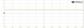
1. The circuit with 5V applied as input operates normally (both VOUT and PG signals are normal).
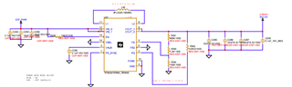
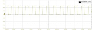
2. However, when checked with an oscilloscope, the circuit that applied 12V as the input does not produce a normal signal and oscillates.
In the circuit, 5.5V should be measured, but due to oscillation, the multimeter measures 5.7~5.8V.
In both cases, the design was based on the guide in the data sheet. What part was wrong?
Below are circuit diagrams for two cases.
Best regard.
12V(Not working)
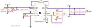
5V(Working)