This thread has been locked.

If you have a related question, please click the "Ask a related question" button in the top right corner. The newly created question will be automatically linked to this question.

TPS65219:without output(It is only outputting three times) AM6442 SERDES0 PCIe

Part Number: TPS65219
Other Parts Discussed in Thread: AM6422, , TPS65220, USB2ANY, TPS62A02

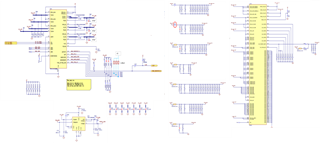
I have a question about the circuit that supplies power to the AM6422 using TPS6521901. The power is only outputted three times before it stops.
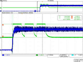
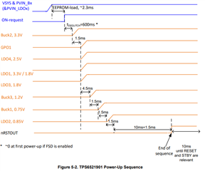
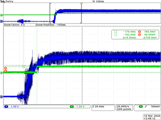
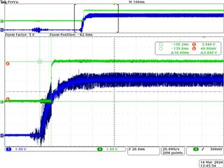
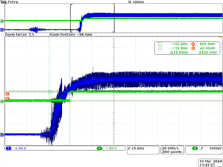
Blue: VSYS(5V)
Green: Buck2(3.3V)


It appears that there is a fault and it is going through two retries before shutting down. In the output voltage waveform, the outputs of Buck3 (1.2V) and LDO2 (0.85V) seem to be abnormal.

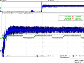
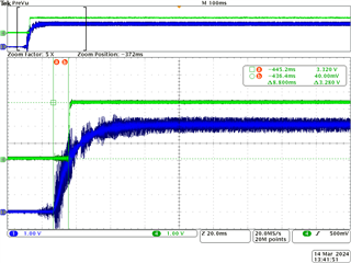
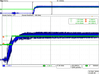
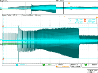
For the 1.2V output:
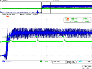
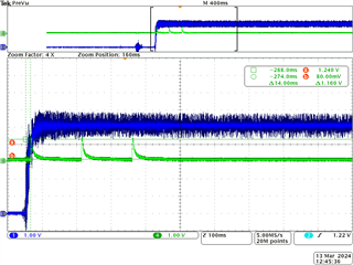

Blue: VSYS(5V)
Green: Buck3(1.2V)

The output voltage drops faster compared to the 3.3V output.

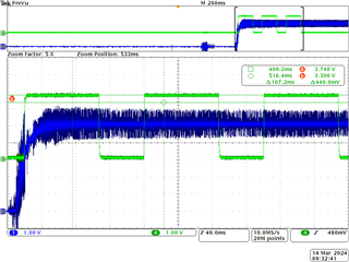
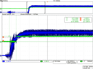
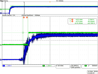
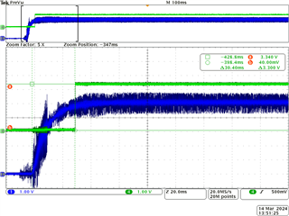
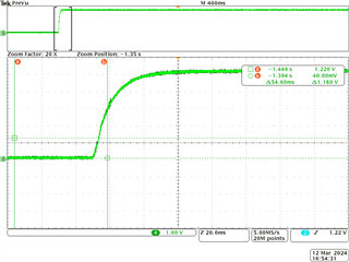
For the 0.85V output:
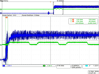
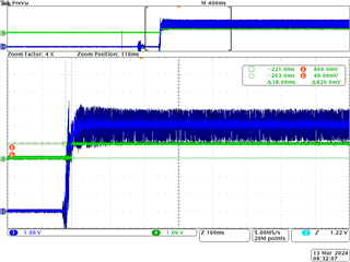

Blue: VSYS(5V)
Green: LDO2(0.85V)

The output voltage rises in a stair-step pattern.
The output voltage reaches around 0.5V.


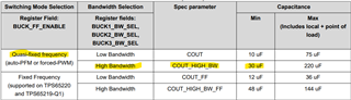
I have referred to the forum link provided and made the modifications to the capacitors for Buck1-3, but there has been no improvement. Please provide advice on how to resolve the issue.
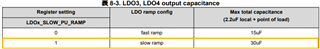
Reference source

e2e.ti.com/.../5043590

  • Hi,

    The device expert is out today and will return tomorrow and should be able to help you with this issue. I will check if someone can respond sooner, but you can expect an answer by latest Wednesday 3/13.

    Best regards,

    Matt

  • Thank you for your reply.

    I would like to share some additional information that I have confirmed.

    It appears that after removing the connections between the power pins of the CPU and the corresponding decoupling capacitors, as well as removing the dummy loads (pull-down resistors) on the power pins, the voltage is being correctly outputted. The RESETOUT_N signal is also being successfully outputted.

    Blue: VSYS(5V)
    Green: Buck2(3.3V)

    Blue: VSYS(5V)
    Green: Buck3(1.2V)

    Blue: VSYS(5V)
    Green: LDO2(0.85V)

    Blue: VSYS(5V)
    Green: RESETOUT_N

    Upon adding the connections between the CPU and the TPS6521901 power sequencing (as shown in the diagram) in the following order: Buck2 -> LDO4 -> LDO1 -> LDO3 -> Buck3 -> Buck1 -> LDO2, the power supply experienced a behavior where it rises three times before dropping when connecting the output of LDO2 (0.85V).
    (At this point, RESETOUT_N is not connected to AM64.)


    Furthermore, from the TRM and datasheet, I found that there were violations in the capacitor requirements for the LDOs. I tried making some changes by reducing the capacitor values as follows, but it did not improve the situation:
    LDO1: 2.2uF -> no change
    LDO2: 24uF -> 14uF
    LDO3: 58uF -> 28uF
    LDO4: 34.4uF -> 24.4uF


    Is it possible that overcurrent is the cause if connecting the CPU to LDO2 results in an "NG" status? LDO2 is only connected to AM64 and not to any other devices.
    (The following power pins on the AM6422 are the only connections to LDO2):
    VDDA_0P85_SERDES0 (P12, P13)
    VDDA_0P85_SERDES0_C (P11)
    VDDA_0P85_USB0 (T12)
    VDDR_CORE (L10, M13)
    VDD_DLL_MMC0 (H14)
    VDD_MMC0 (K13)

    I would appreciate any advice or suggestions for resolving the issue.

  • Hi,

    Could you confirm all the PMIC rails stay ON after all loads are disconnected? What output voltage do you need on LDO1, 3.3V or 1.8V? 

    What is the current state of the multi-function pins (VSEL_SD, MODE/RESET, MODE/STBY)? These pins cannot be left floating. 

    Thanks,

    Brenda

  • Hello

    With all connections to the CPU disconnected, Buck1-3, LDO1-4, and RESETOUT_N remained ON.
    At this time, the voltage of LDO1 is 1.8V.

    The VSEL_SD pin was floating.
    After pulling up the VSEL_SD pin to 5V, the voltage of LDO1 changed, but the inability to maintain the ON state symptom did not improve.
    When only the 0.85V CPU connection is disconnected, it outputs normally, but when 0.85V is connected to the CPU, it stops outputting again.

    Blue: VSYS(5V)
    Green: LDO1(3.3V)

    Blue: VSYS(5V)
    Green: LDO2(0.85V)

    In my circuit, the output of LDO1 is unused. (Buck2 supplies 3.3V to VDDA_3P3_SDIO and is connected to CAP_VDDSHV_MMC1 and VDDSHV5.)
    When R447 is removed, each power supply can maintain the ON state. However, when R447 is connected, each power supply cannot maintain the ON state.
    R447 is connected between LDO2 and AM64.

    The voltage waveforms of Buck1-3, LDO1-4, and RESETOUT_N when R447 is removed.


    Blue: VSYS(5V)
    Green: Buck1(0.75V)

    Blue: VSYS(5V)
    Green: Buck2(3.3V)

    Blue: VSYS(5V)
    Green: Buck3(1.2V)

    Blue: VSYS(5V)
    Green: LDO1(3.3V)

    Blue: VSYS(5V)
    Green: LDO2(0.85V)

    Blue: VSYS(5V)
    Green: LDO3(1.8V)

    Blue: VSYS(5V)
    Green: LDO4(2.5V)

    Blue: VSYS(5V)
    Green: RESETOUT_N


    I measured the current on the path from LDO2 to the CPU, but it doesn't appear to have any spike currents exceeding the current limit.

    Cyan: LDO2_current
    Green: LDO2(0.85V)


    I believe the possibility of implementation failure is low since similar symptoms are occurring in other prototype boards as well. Is it possible that the AM64 is being damaged by power supply turn-on? For example, is it possible that latch-up occurs within the pin where the LDO2 of the AM64 is connected in this circuit?

    Please let me know if there is anything I can check to help resolve the issue.

    Thank you.

  • Hi,

    Could you share the schematic in a searchable PDF instead of an image? The schematic can also be shared by private E2E message if that is preferred. In the meantime, here is my feedback:

    • VSEL_SD cannot be left floating. LDO1 is configured as bypass and the output voltage is set by the VSEL_SD pin with the following polarity:
      • VSEL_SD HIGH: LDO1=3.3V (behaves as bypass and requires PVIN_LDO1=3.3V)
      • VSEL_SD LOW: LDO1=1.8V (behaves as a fixed 1.8V LDO)

    • Why is Buck2 supplying VDDA_3P3_SDIO, CAP_VDDSHV_MMC1 and VDDSHV5? The AM64 has an internal LDO that supplies the SD card IO voltage. You just need to supply VDDSHV5 with the output of CAP_VDDSHV_MMC1. 

    • Here is the link to the AM64 SK EVM. You can use it as a reference to understand the connections between PMIC and processor. Link: https://www.ti.com/tool/SK-AM64B

    Thanks,

    Brenda

  • Hi,

    I have received the circuit diagram through the private message in E2E.

    Regarding VSEL_SD,
    I have confirmed that by pulling up VSEL_SD, 3.3V is outputted to LDO1. When LDO2 is not connected to AM64, the rail remains on. However, when LDO2 is connected to AM64, the rail does not remain on.

    Regarding the connection of Buck2,
    I apologize for the insufficient explanation regarding the connection of "Buck2". "Buck2" is connected to "VDDA_3P3_SDIO". "CAP_VDDSHV_MMC1" and "VDDSHV5" are connected, but they are not connected to "Buck2".

    I have reviewed the documentation for the AM64 SK EVM. While the AM64 SK EVM uses the TPS6522053RHBR, I would like to clarify that the specifications for LDO2 are not equivalent to the TPS6521901.

    Regarding the presence of a bead core between the PMIC's LDO2 and AM64 on the AM64 SK EVM, I understand that you tried implementing it in your circuit, but the rail did not remain on.


    I conducted the following tests with LDO2 disconnected from AM64 on the PMIC:
    A: Drawing current from LDO2 using an electronic load... Even with an output current of around 400mA, the rail remained on.

    B: Adding capacitors to LDO2... I added capacitors ranging from 10uF to 100uF in 10uF increments, but in all cases, the rail remained on.

    With LDO2 disconnected from AM64, I powered on the PMIC and supplied 0.85V from a stable power source to AM64. Due to a sequencing issue, I did not perform a reset release for AM64.
    No surge current was observed in the 0.85V path. Additionally, the power rail of the PMIC remained on.


    I found an example circuit, BeaglePlay, that uses TPS6521901. BeaglePlay utilizes AM62, which has different connections compared to AM64 (such as the number of pins for VDDR_CORE and the presence of VDDA_0P85_SERDES0). Does this difference become critical when using TPS6521901?

    In the TPS6521901 lineup, it appears that TPS6521907 can supply 0.85V to VDD_CORE and use a common source (Buck1) with VDDR_CORE and others.
    If TPS6521901 is used for power supply in AM64, are there any specific settings or modifications that need to be made on the AM64 side for TPS6521901 (VDD_CORE=0.75V) and TPS6521907 (VDD_CORE=0.85V)?

    Thankyou

  • Hi,

    Thanks for sharing an update. Here is my inputs: 

    • LDO1 will not output 3.3V unless VSEL_SD is pulled up and PVIN_LDO1 is connected to a 3.3V input supply. In your schematic, PVIN_LDO1 seem to be connected to a 5V supply. 

    • TPS6521901 has the Bucks configured to operate in Quasi-fixed frequency and high bandwidth. This configuration requires a minimum of 30uF local output capacitance. 47uF per Buck is typically used. 

    • TPS6521901 is used for VDD_CORE=0.75V and TPS6521907 is used for VDD_CORE=0.85V. When VDD_CORE operates at 0.85V, the same PMIC rail (Buck1) is used to supply both CORE rails (VDD_CORE and VDDR_CORE). 

    • Are you able to improve the 5V pre-regulator to get a cleaner waveform? I see a lot of noise on VSYS.

    • What is currently the total (local + POL) output output capacitance on LDO2? 

    • Some of the scope captures show LDO2 output only getting approximately 0.5V while other captures show LDO2 output closer to 0.85V. What did you change in the design that causes different output voltage on LDO2? 

    Thanks,

    Brenda

  • Hi,

    Thank you for your inputs.


    >LDO1 will not output 3.3V unless VSEL_SD is pulled up and PVIN_LDO1 is connected to a 3.3V input supply. In your schematic, PVIN_LDO1 seem to be connected to a 5V supply.

    I understand that when outputting 3.3V, it operates in bypass mode.
    Since PVIN_LDO1 is connected to the system power (5V), I will change VSEL_SD to PULL DOWN and configure it to output 1.8V.


    >TPS6521901 has the Bucks configured to operate in Quasi-fixed frequency and high bandwidth. This configuration requires a minimum of 30uF local output capacitance. 47uF per Buck is typically used.

    I connected a 47uF capacitor to the outputs of Buck1-3. I will send you the updated circuit diagram via private message on E2E.
    However, even after connecting the 47uF capacitor to the outputs of Buck1-3, the rail did not remain on.


    >TPS6521901 is used for VDD_CORE=0.75V and TPS6521907 is used for VDD_CORE=0.85V. When VDD_CORE operates at 0.85V, the same PMIC rail (Buck1) is used to supply both CORE rails (VDD_CORE and VDDR_CORE).

    Can TPS6521907 be used with both AM62 and AM64?
    The Application Note "Powering the AM62x with the TPS65219 PMIC" mentions TPS6521907, but the Application Note "Powering the AM64x with the TPS65220 or TPS65219 PMIC" does not mention TPS6521907.
    Is there any difference in power supply between AM62 and AM64?
    If TPS6521907 is compatible with AM64, I would like to consider using TPS6521907 (VDD_CORE=0.85V) in the next design.


    >Are you able to improve the 5V pre-regulator to get a cleaner waveform? I see a lot of noise on VSYS.


    The waveform of VSYS has a lot of noise due to using a simple probe (CH1).
    However, when using the probe (CH4) that was originally used for the output of LDO2, the noise appears to be less.


    Green:VSYS(5V)


    >What is currently the total (local + POL) output output capacitance on LDO2?

    Total = 14.0uF (2.2uF + 11.8uF)


    >Some of the scope captures show LDO2 output only getting approximately 0.5V while other captures show LDO2 output closer to 0.85V. What did you change in the design that causes different output voltage on LDO2?

    If the power input pin of LDO2 is not connected to the power input pin of AM64, the output of LDO2 will be 0.85V. In this case, all power rails (Buck1-3, LDO1-4) will remain on.

    When the power input pin of LDO2 is connected to the power input pin of AM64, the output of LDO2 will only be 0.5V. Additionally, not all power rails will remain on.

    Implementing R447 will connect the power input pins of LDO2 and AM64. Removing R447 will disconnect the power input pins of LDO2 and AM64.


    I want to run AM64 in my circuit, but I cannot power it on when connecting LDO2, so the output of LDO2 is unusable. Therefore, for now, I am considering supplying 0.85V to VDDR_CORE from another regulator IC.

    Are there any important points to consider when supplying 0.85V to VDDR_CORE from another regulator IC? For example, are there any specifications regarding the transition time from turning on the 0.75V rail to turning on the 0.85V rail?


    Thank you

  • Hi,

    TPS6521907 can be used for both, AM62x and AM64x. When using TPS6521907, VDD_CORE and VDDR_CORE are both supplied by Buck1 (0.85V). In this scenario, LDO2 becomes a free resource. 

    I would not recommend supplying VDDR_CORE with a separate IC as it has specific sequence requirements. Here is a capture from the AM64x data sheet:

    I have discussed this issue with the processor team and they would like to see the full schematic showing all the interfaces related to the 0.85V rail. Are there any interfaces that are active when the SOC is powering (Example: SERDES0 or ADC or any other inputs)? 

    Thanks,

    Brenda

  • Hi,

    >TPS6521907 can be used for both, AM62x and AM64x. When using TPS6521907, VDD_CORE and VDDR_CORE are both supplied by Buck1 (0.85V). In this scenario, LDO2 becomes a free resource.

    Currently, my board is equipped with TPS6521901. Is there a way to change the voltage setting of Buck1 on TPS6521901 to 0.85V (the same voltage as TPS6521907) when TPS6521901 starts up?
    If it is possible to change the voltage during the startup of TPS6521901, I would like to change Buck1 to 0.85V and supply it to VDD_CORE and VDDR_CORE.

    If I can get my hands on the TPS6521907, I am considering replacing the TPS6521901 with the TPS6521907.
    Are there any other precautions to consider besides disconnecting the output of LDO2 from AM64 and supplying it from Buck1 to power pins such as VDDR_CORE?


    >I would not recommend supplying VDDR_CORE with a separate IC as it has specific sequence requirements. Here is a capture from the AM64x data sheet:

    I understood AM64 need to keep "VDDR_CORE < VDD_CORE + 0.18V".
    If I supply a voltage of 0.85V to VDD_CORE and VDDR_CORE from a different IC, would there be any issues with the sequence?
    I am considering using the RESETOUT_N from the PMIC as an enable for another IC and using its POWERGOOD signal to deassert the reset of the AM64.


    >I have discussed this issue with the processor team and they would like to see the full schematic showing all the interfaces related to the 0.85V rail. Are there any interfaces that are active when the SOC is powering (Example: SERDES0 or ADC or any other inputs)?

    Thank you for the discussion with the processor team.
    I sent you the full circuit diagram via private message on E2E.


    Thank you.

  • Hi,

    The AM64x processor doesn't support dynamic voltage scaling (DVS) so the required VDD_CORE voltage (0.75V or 0.85V) needs to be set by default.

    I have shared the full schematic with the processor team and I'm waiting for their feedback.  

    Thanks,

    Brenda

  • Hi,

    I understand that the voltage of VDD_CORE should not be changed when AM64 is ON.

    Is there a way to set the default voltage of Buck1 in TPS6521901 to 0.85V?
    Alternatively, if I don't replace it with TPS6521907, will I not be able to achieve a voltage of 0.85V for Buck1?

    Thank you

  • Hi,

    The output voltage of Buck1 can be re-programmed using one of the programming board at the following link: https://www.ti.com/tool/TPS65219EVM-SKT. The programming guide also explains the in-circuit programming steps using an external USB2ANY. Here is the link: https://www.ti.com/lit/pdf/slvucm5

    If 0.85V is needed on Buck1, it might be easier to replace the PMIC with TPS6521907 than re-programming the TPS6521901.  Let us know if there are any questions. 

    Thanks,

    Brenda

  • Hi,

    Thank you for the reference to Buck1's modification method.
    I understand that to modify Buck1, it is necessary to have a microcontroller or processor other than AM64 that can access the PMIC via I2C.

    I would like to evaluate by replacing TPS6521901 with TPS6521907, so I am currently requesting confirmation of procurement from the supplier.

    Thank you

  • Thanks for sharing an update. If there are no more questions on the PMIC, we will close this E2E. Feel free to respond to this last message or submit a new E2E if there are additional questions related to the PMIC. 

    Thanks,

    Brenda

  • Hi,
    I have successfully powered the AM64 using two methods:

    1.Using TPS62A02:

    I removed the connections between TPS6521901's Buck1, LDO2, and AM6422. Instead, I supplied 0.85V generated by TPS62A02 to VDD_CORE, VDDR_CORE, VDDA_0P85_SERDES0, VDDA_0P85_SERDES0_C, VDDA_0P85_USB0, VDD_DLL_MMC0, and VDD_MMC0.
    I connected TPS6521901's nRSTOUT to TPS62A02's EN, and integrated TPS62A02's PGOOD into the reset circuit to ensure the sequence is met.


    2.Adding a resistor between LDO2 and GND:

    I added a 10-ohm resistor between TPS6521901's LDO2 and GND. The output of LDO2 rises in the order of 0V -> 0.1V -> 0.85V. Each power rail remains on.

    With the connection between TPS6521901's LDO2 and AM6422 removed, I measured the voltage of VDDR_CORE on the AM64 and observed a waveform gradually increasing from 0.2V to 0.5V. Since there is no supply from TPS6521901, it appears that the charge is being supplied from the AM64. The datasheet of TPS6521901 mentions that it cuts off the power when detecting residual voltage. Therefore, it is possible that the voltage rise in the VDDR_CORE path was identified as residual voltage, leading to power cutoff. To address this, I added a resistor between LDO2 and GND to ensure that the voltage rise does not exceed the residual voltage threshold.

    Are there any concerns regarding this approach for TPS6521901 and AM6422? The expected current consumption for TPS6521901's LDO, considering the consumption of the AM64 and the resistor, is below 200mA (AM6422 : 51mA + resistor : 85mA). The power supply voltage of AM6422 satisfies the condition of VDD_CORE + 0.18V < VDDR_CORE.


    By the way, TPS6521907 has been ordered but has not yet arrived, so it has not been evaluated.


    Thank you.
    Akihiro

  • Hi,

    Thanks for sharing the information! The two methods described in your previous message are considered work around, part of the debug process but they don't fix the issue in your PCB. We don't recommend any of those methods for the final design. I'm suspecting the issue is not related to the PMIC because it works as expected when LDO2 is disconnected from the AM64 processor.

    The Sitara processor team took a look at the latest schematic that was shared and provided the following comments:

    • SERDES0 and ADC: we do not have a way to confirm that the SERDES0 and the ADC0 inputs are not available before the SOC power ramps. Customer will have to verify and confirm or disconnect the ADC inputs or the SERDES0 inputs to verify.

    Thanks,

    Brenda

  • Hi,

    As you mentioned, when we disconnect the connection between LDO2 and the processor, the PMIC is functioning correctly.
    Therefore, it seems that there is an issue with the circuitry on the processor side. I will create a new thread on the E2E forum specifically for discussing the processor and peripheral circuitry.

    Thank you for the comment from the Sitara processor team.

    We will verify the inputs of SERDES0 and the ADC0 during the unexpected rise of VDDR_CORE voltage.

    > We don't recommend any of those methods for the final design.
    Is it because the power supply issues with the processor side have not been resolved?


    Thank you.
    Akihiro

  • That sounds like the right next step to submit an E2E to the Sitara processor team so they can provide feedback on the remaining connections to the MPU and peripherals. In the new thread, please specify that the PMIC is able to successfully complete the power-up sequence when LDO2 is disconnected.  

    The work arounds you had implemented are just not recommended for the final design because they don't fix the issue in your PCB, the MPU sequence is not fully controlled by the PMIC and it is unknown how that issue could be affecting the reliability of the ICs.  

    Thanks,

    Brenda

  • Hi,

    I have checked the input of SERDES0.
    During an unexpected rise in VDDR_CORE voltage, a signal was being supplied to SERDES0_REFCLK0.
    When the circuit of SERDES0_REFCLK0 was configured similar to the EVM, the unexpected rise in VDDR_CORE voltage from AM64 was eliminated.

    It seems that a charge was being supplied to the 0.85V line from either VDDA_0P85_SERDES0 or VDDA_0P85_SERDES0_C, causing the PMIC to recognize it as residual voltage and enter FAULT mode.

    The problem has been resolved successfully, and now AM64 can be booted without adding a 10-ohm load.

    Thank you for your assistance in resolving the issue.

    Thank you
    Akihiro

  • Awesome! Thanks for sharing the resolution of the issue. Let us know if you need further assistance. 

    Thanks,

    Brenda

  • Hello Akihiro

    Could you please summarize the changes that was done.

    I can get the changes validated by the device expert.

    Have you had a look at Errata i2326 ?

    Regards,

    Sreenivasa

  • Hi,

    I have made modifications to my circuit as shown in the diagram.

    before


    after


    I referred to the TDMS64EVM circuit for guidance.
    Since I didn't have a 49.9-ohm resistor available, I used a 51-ohm resistor as a substitute.


    > Have you had a look at Errata i2326 ?

    It appears that Errata i2326 provides information about considerations when supplying 100MHz from the MAIN_PLLx within the AM64.
    In my circuit, I have prepared an external REFCLK generator outside of the AM64 to supply the 100MHz, so I believe this errata does not apply to my circuit.

    Thank you.

    Akihiro

  • Hello Akihiro

    Thank you for the inputs.

    Appreciated.

    Regards,

    Sreenivasa