This thread has been locked.

If you have a related question, please click the "Ask a related question" button in the top right corner. The newly created question will be automatically linked to this question.

TPSF12C3-Q1: Higher injection current design

Part Number: TPSF12C3-Q1

Hello 

Our customer is using TPSF12Cx-Q1 on a system like this  .

On the right hand is the high voltage battery, on the left is the driver.

They need a larger injection current. I wonder if you have any design for this need.

  • Hi Yuhao,

    Is the picture below correct where the HV batter is on the left and the driver on the right?

    If the picture above is correct, the AEF should be connected as shown below:

    To answer your question, no, we do not have any designs with AEF to increase the injection current. AEF is basically a capacitive multiplier. 

    Ben

  • Hello Ben,

    Our customer from another team also wanted a design to increase the insert current. I wonder if we can have a design to inrease the  current or the next generation product could fulfill the need.

    Best regards,

    Yuhao

  • Hi Yuhao,

    By adding a buffer stage to increase the output current will definitely change the AEF loop stability. What is the switching frequency of this application? Based on the figure that is shown, the application seems to be a motor drive/traction inverter. Just a reminder, TPSF12C3-Q1 has a frequency of interest from 150kHz to 3MHz. The motor drive/traction inverter operates at lower frequencies (~20kHz). If you can provide us more details, it will help determine if AEF is an option for their application. Thanks,

    Ben

  • Hello Ben,

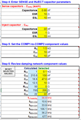
    Our customer used the parameter shown below 

    and get the result like this, could you please help with the parameter?
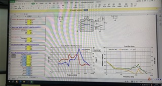
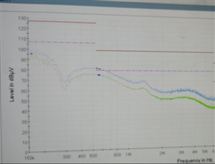
  • Hi Yuhao,

    Can you provide us the quickstart calculator? In the pictures, I do not see the AEF gain loop plot which determines whether the AEF loop is stable or not. I noticed that the "regulator-side Y-capacitors" is set at 147nF. Is that correct? That seems a bit large for the AEF IC. In the step 7 picture, the INJ pin current is a lot higher than the 80mA current the IC can deliver. Also, the INJ pin voltage swing is 11.7Vp-p which is too high and is probably causing the INJ pin to saturate (clip).

    My suggestion is before adding AEF, the customer should try several experiments (with the filter that will be used in their application):

    Before the customers jump right into using the AEF IC, we ask the customers to perform several simple task. To test and see if CM noise can be mitigated, we ask to place 47nF-100nF of Y-capacitance (on line and neutral or on DC+ and DC-) between the chokes and measure EMI. If there is significant reduction of CM noise, then we know that the system has a lot of CM noise. We also ask the customer to place larger X-capacitors or add a series DM inductor and re-measure EMI. If there is significant reduction of DM noise, then we know that the system has a lot of DM noise.

    By adding 47-100nF of Y-capacitance between the chokes, it mimics of having AEF amplifying the CINJ capacitor by 10-20X.

    Ben  


  • Hi Yuhao,

    Are there any updates?

    Ben

  • Hello Ben,

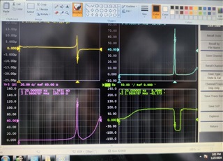
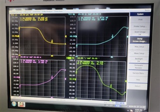
    Here is our customer's test result:

    They changed the parameter increasing the phase margin and get the result:

    The Magnetic loop curve using 1.5uH ferrite is as follows, a little bit peak because they can't remove the xy capacitor, it should be flat:

  • Hi Yuhao,

    Thanks for the info. Can you tell me the details of these plots? Are they with AEF or are the results from increasing the X or Y capacitances of the filter?

    Ben

  • Hello Ben,

    They are with the AEF. Any comment on the result?

    Yuhao

  • Hi Yuhao,

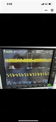
    I really cant say based on the plots. Before the customer uses AEF, have the customer add Y-capacitance to GND and see if there are any improvements when measuring EMI. Also, can the customer take a scope shot of the INJ pin?

  • Hi Yuhao,

    Are there any updates?

    Ben

  • Hi Yuhao,

    Please let me know if there are no further questions regarding this topic. If not, can you kindly close the thread by clicking on "resolved"? Thank you,

    Ben

  • @Ben, should the 47-100 nF Y-capacitor between the CMCs be kept when the active filter is installed (such that we have higher Cinj capacitor in practice) or should it be removed if the active filter is installed? If former, how/where do we put this capacitor in the spreadsheet?

    Another question I have is if saturation of the Cinj pin could lead to the amplification of the emissions or does it just not work as effective as expected?

  • Hi Baris,

    Can you start a new thread? Thanks,

    Ben