This thread has been locked.

If you have a related question, please click the "Ask a related question" button in the top right corner. The newly created question will be automatically linked to this question.

UCC27624: Isolated gate driver for LLC full bridge converter

Part Number: UCC27624
Other Parts Discussed in Thread: UCC21542,

Good day Mazany and you all. 

Am making an full bridge (mosfets) LLC resonant converter for a solar inverter application (boosting from 48V nominal to 380V output max power 1kW). 

Currently, I have made this LLC converter using the UCC21542 gate driver to drive the mosfets. However I realise that when I provide the VDD voltage (about 12V) to the gate driver before starting the switching, this same voltage gets measured across the resonant capacitor. 

My questions are below

1) Did I use the wrong gate driving method to drive the full bridge?

2) Should I be using the transformer coupled gate driver for driving the full bridge LLC converter e.g the UCC27624, since I see all TI's reference designs for the LLC use the transformer coupled method. 

3) Please explain where I can use the transformer coupled gate drivers and not the capacitive Isolated gate drivers such as the UCC21542? 

  • Hi Paul,

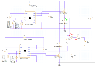
    Can you share a schematic? If you are using a bootstrap supply, I think that could explain the voltage. These nodes are floating in this condition so the voltage will be set by small leakage currents. In simulation, adding pulldown resistors resolved this:

    Please ignore the component values; they are placeholders for this quick test. This resulted in the voltage on HS being ~50mV and the voltage across the cap being exactly 0V. 

    On the other hand, it is probably safe to ignore the voltage also depending on the requirements. It should go away once switching starts.

    1) Did I use the wrong gate driving method to drive the full bridge?

    You can drive the full bridge with isolated drivers, non-isolated half-bridges, or the gate drive transformer method. It just depends on the requirements, but all of them can work. 

    2) Should I be using the transformer coupled gate driver for driving the full bridge LLC converter e.g the UCC27624, since I see all TI's reference designs for the LLC use the transformer coupled method. 

    The isolated driver will also work and is also a popular method. Have you read the gate drive transformer app note? There are pros and cons to each method and its up to your own priorities/needs for the system. 

    3) Please explain where I can use the transformer coupled gate drivers and not the capacitive Isolated gate drivers such as the UCC21542? 

    I'm not sure if there is a strict limitation. There are voltage/isolation limitations to the isolated driver, and the transformer will set the same limitations for the transformer coupled gate drive. I think a major component of the decision is usually the cost of transformers in the system. The transformer coupled gate drive probably needs 2 pulse transformers for a full bridge, while the iso driver needs ~3 if you use a flyback bias supply. I can't say for certain which will be the best in terms of cost/performance.

    Thanks,

    Alex M.