This thread has been locked.

If you have a related question, please click the "Ask a related question" button in the top right corner. The newly created question will be automatically linked to this question.

LM25184-Q1: PSR Flyback converter design

Part Number: LM25184-Q1
Other Parts Discussed in Thread: LM5185-Q1, LM5185, LM5155, PMP22151, PMP, LM5156

Hi, 

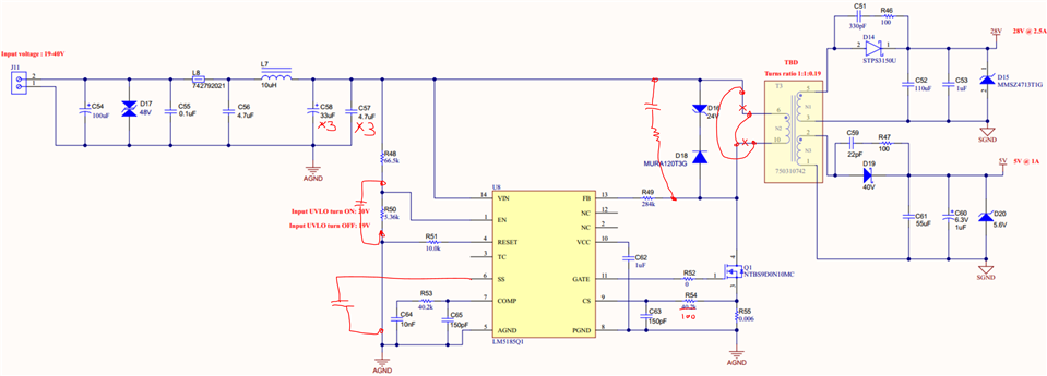
I am looking for the low-cost DC-DC Isolated converter, Where the supply input is 19V to 40V max, nominal input 28VDC, Multioutput configuration = 24VDC @ 3.5A for 24VDC motor max and 5VDC @ 1A output for down conversion power rails, I am working with couple of PSR flyback converter topology for cost-effective solutions. Let me know can we achieve this requirement using PSR flyback topology controllers? Also please guide/suggest me the best cost-effective and high efficiency controller/solutions for this requirement on high priority. 

The BOM cost target is < $10. 

Regards,

Ravi

  • Hi Ravi,

    Thank you for reaching out.  Your total load is about ~90W, and the LM25184-Q1 cannot support it due to its internally fixed current limit at 4.1A typical.  

    Instead, I would recommend the LM5185-Q1 PSR flyback controller, which employs an external FET and current sense resistor.  Please visit  https://www.ti.com/product/LM5185-Q1 for details.  You can also use the design calculator to help you in design. The calculator can be found at https://www.ti.com/tool/download/LM5185-DESIGN-CALC.

    Best Regards,

    Youhao

  • Hi Youhao, 

    Thanks for your suggestions, I can see the given Webench designer LM5185-Q1 maximum current limit 2A, means i can not use the tool more than 2A for LM5185. I need to simulate my design for 24VDC @ 90W or 34VDC at 2.5A maximum. I am specifically looking into flyback PSR topology due to low cost design. please advice me if i am missing anything here. Share if any reference design available for my requirements. 

  • Hi Youhao, 

    I have modified my design requirements for 28VDC @ 2.5A 70W power source for DC motor. Could i use PMP22151 70W flyback reference design 28V @2.5A , Hope LM5155 will support for this. Please let me know your recommendation on better cost effective solution controllers and reference design if any available. Please correct me if any corrections in my proposal.  

  • Hi Ravindran,

    Please note that the PMP22151 requires the opto coupler.  You should consider the LM5185 in a PSR flyback design.  At full load, the PMP22151 operates in CCM while the LM5185 will operate in BCM, therefore the transformer in the PMP would not support the peak current at 19Vin and full load.

    Instead, I found Coilcraft MSD1514-472 which can be used to support your design. I also generated a design by using our design calculator for your reference, which is attached below.  In the calculator file, the said magnetics and a vendor's MOSFET  (NTBS9D0N10MC) are used.  Please ignore the efficiency curve because the transformer losses were based on a different material in the background calculation which is not applicable to the MSD magnetics.  

    Good luck in your project.

    90W PSR Flyback--LM5185-DESIGN-CALC.xlsx

    Youhao

  • Hi Youhao, 

    I appreciated your support and proposal.

    I have modified the design for dual output configuration for 5V @1A in the existing calculations. Please suggest the proper transformer selection and MOSFET, also just changing the multi output (dual config) will this affect any of the converter performance or any issue will arise, please let me know your review on attached calculation screenshot below.  

    Also, I would like to inform you the main input source capacity is 100VA transformer 24VAC or 24VDC battery source. I can see in the calculation the Vin max power reached at 95W. which is very close to the source. Please advise on calculated efficiency impact and how to improve the input power consumption. 

  • Hi Ravindran,

    For dual outputs (28V and 5V), I do not find an off-the-shelf transformer, and you have two choices. One is implement the design as proposed yesterday for 28V single output, then employ a buck regulator to produce 5V from the 28V rail.  The other is design dual output flyback as you did with the calculator, and reach out to your preferred magnetics vendor to make the required transformer for you to use. 

    Regarding your question 95W, it is the max output power capability of the design if you choose that transformer (4.7uH) and turns ratio, and use that Rcs resistor (6mOhm), not the input power it takes. 

    Thanks,

    Youhao

  • Hi Youhao, 

    Thank you for the clarification. Please review the below screenshot attached schematic diagram as per the design calculation inputs. (Transformer part yet to decide as per your suggestions, at present just representation I captured). 

    LM5185Q1- PSR Flyback design 

    Another my concerns is efficiency of the above design, I am looking for the design efficiency >90% at nominal input voltage 28VDC or 34VDC and also the stability. What is the maximum efficiency we can achieve by the above design and what is the switching frequency used for transformer selection. Please provide your suggestions if any improvisation further needed on this circuit. 

    Thanks & regards, 

    Ravi 

  • Please see my review markup. A error is the transformer polarity.  Swap the pins.  Also, please reserve those component positions on your PCB in case you need them after test.  By doing this you can avoid having to do a PCB revision.   

    Since the majority power is in the 28Vout, I think you should be able to get 90% efficiency.   See the calculator in which the switching frequencies are plotted.

    Thanks,

    Youhao

  • Hi Youhao, 

    Thanks for the review. I will modify the schematic as per your review comments also work with transformer vendor to complete the design. 

    I will come to you if I get any comments/queries from our internal project reviews. 

    Regards,

    Ravi 

  • Hi Ravi,

    Thank you, and feel free to contact us if we can be of further assistance.  Good luck in your project.

    Regards,

    Youhao

  • Hi Youhao, 

    I need to redesign my circuit for 140W power due to higher current requirement at the load. Please find the change in the load specification (Motor)

    Input ; 24VAC or 24VDC ±30%

    Output : 34VDC 140W

    Can we use LM5185-PSR flyback converter design for this power rating. I need low cost high efficient converter design. please let me know your suggestions.  

  • Hi Ravindran,

    140W can be a stretch but you can design with the LM5185 by choosing a small Rcs resistor and maybe use parallel MOSFETs.  In general flyback is the most cost effective solution for power level up to 75W.  For higher power, the transformer can become large, losing the flyback advantages over other topologies like a forward or half-bridge.  However the LM5185 can still support your design if you want to use PSR to save the opto.   Please start your design using our design calculators.

    Best Regards,

    Youhao

  • Hi Youhao, 

    Thank you for your suggestions. I will come back to you for calculation review. 

  • Hi Youhao, 

    Based on our internal team review, we are set with the flyback design output voltage is 30VDC @ 4A Current, Peak current 6A support for motor start up current.

    Since the PSR flyback topology DC-DC converter recommended for <100W, could you please suggest the AC to DC low-cost Flyback converter switching IC for the above specification. I will work on that calculation part and come to you for review.  (Input remains same)

  • Hi Ravindran,

    In this case, if your want to design in flyback, you should stay with the LM5185. Chose the same coilcraft coupled inductor that I mentioned earlier. 

    TI does have other flyback controllers like the LM5156 but it requires an opto coupler to get the similar output regulation accuracy as the LM5185 without the opto coupler. 

    Hope this clarifies.

    Best Regards,

    Youhao

  • 125W PSR Flyback--LM5185-DESIGN-CALC.xlsx

    Hi Youhao, 

    Herewith attached the 125W_PSR_Flyback_LM5185_Calculation for your review, I need your help on flyback transformer calculation part and efficiency curve verification. Expected efficiency 85-92%. Please let me know your comments and suggestion to finalize the design. 

    Output1: 30V @ 4A

    Output 2:  5V @ 1A for digital rail voltages. 

  • Hi Ravindran,

    Thank you for designing with the LM5185.  I reviewed your calculator file, it is looks okay. Some suggestions:

    • DCLAMP choose 36V, so you can use 100V MOSFETs.
    • RFB should be 255k, not 284k.
    • Reserve the option of using external SS by adding a capacitor position at SS pin.
    • The calculator efficiency curve is wrong because the back ground refers to a wrong core losses material.  Usually a well designed transformer should not dissipate more than 5% of the total power.
    • More concern is in two devices:  the 20V rail rectifier diode, and the power MOSFET.  You may consider to reserve 2x MOSFET in parallel on PCB to share the power dissipations.  125W is not a small power.   Make sure you do not overlook the diode power dissipation.  It will be VF x 4A. 
    • When you design your PCB, refer to the PCB design guidelines, and also our EVM layout example.

    Good luck in your project.  

    Best Regards,

    Youhao