This thread has been locked.

If you have a related question, please click the "Ask a related question" button in the top right corner. The newly created question will be automatically linked to this question.

UCC28070: Input current waveform abnormal

Part Number: UCC28070

Hi Sir,

At present, I use your UCC28070 chip to make PFC product.

When the power reaches above 3.6kW, the input current waveform is abnormal in a certain period, and the other periods are normal.

Abnormal current flow is very random, as follows.

Any ideas on how they can improve this?

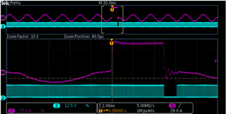
  Ch2:Vgs; Ch3: Input current

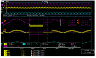
 Ch1: Inductor current; Ch2: Input Voltage; Ch3:Input current

Thanks.

  • Hello Phil, 

    Thank you for bringing this issue to the forum. 

    I believe that this problem is caused by saturation of one or both of the current sense transformers (CTs).
    In the second screen-capture, the current scales are different, so it is a little difficult to compare, but it looks like the input current is about twice as high as the inductor current, so I think both CTs are saturating.

    When a CT saturates, no current information can be detected at the CSA or CSB inputs, so CAOx error voltage goes to maximum and PWM duty cycle goes to maximum.
    The current is limited only by the AC source current-limit, which can be seen where the AC input voltage has dropped close to zero. 

    After about 7ms in this condition, the PFC output voltage has reached the OVP level and switching shuts down (and input current goes to zero) until the OVP clear level is reached. Then switching resumes.  During the off-time, the CTs have had a chance to fully reset so they are no longer in saturation and normal PFC operation also resumes.  

    Eventually, temperature and current conditions change enough so that the CTs reach saturation again, and this problem appears to happen at random. 
    I believe the solution is to examine the current-sense transformer and associated reset circuit and adjust so that reset is always possible and no saturation of the CT is possible.  

    Please review the Section 8.2.2.7 (pages 32-34 in the UCC28070 datasheet) which describes the volt-second balance requirements for CTs to avoid saturation. 
    Surprisingly, this situation is more likely to occur near the zero crossings because there is mostly on-time and very little reset time, and the CT output diode develops significant voltage across the magnetizing inductance.   
    Please see if your CT reset circuit develops sufficient voltage during the PWM off time to reset the CT.  

    Regards,

    Ulrich

  • Hi Ulrich,

    Thank you for the detailed response!

    When this problem occurs, the measured MOS PWM duty cycle is the maximum value

    The reset circuit uses a resistor and diode in series
    I made the resistor larger but no improvement

    Please give me some advice.

    I will respond to you as soon as possible. Thank you!

  • Hello Phil, 

    Thank you for the additional information. 

    I suggest to follow the signal chain back to find the source of the problem.
    Does this issue happen on both PFC channels (Phase-A and Phase-B) or on only one channel? 

    Refer to the Functional Block Diagram in the datasheet. 
    During the problem, PWM duty cycle is maximum because CAOx output is maximum. 
    Check CAx inputs (+) and (-) to see why COAx is maximum.

    The (+) input is the IMO pin voltage.  Check Vimo to make sure that this waveform follows the VINAC voltage during the problem.
    I expect that when the input current goes to ~75A (during the problem time) the AC source voltage will fall as seen in the AC waveform. 
    When this happens, VINAC will also fall, and so Vimo should also fall.  Please verify this. 
    When the reference voltage for the current amplifiers (CA1, CA2) falls, CAOx should fall as well.  I don't expect the output to go to maximum ~5V.

    Since I think that Vimo is lower than normal during the problem, CAOx can be max only if the (-) input is even lower than the (+) input. 
    And the (-) input can be lower only if there is not enough signal level at CSA or CSB. 

    And low signal level at CSx (when inductor current is > 40A) is possible if
    a)  the CT is saturated, or 
    b)  Intermittent open circuit between CSx input and one of the Rsense signals, or
    c)  Intermittent short circuit across one of the Rsense resistors.  

    It is unlikely to have synchronized intermittent opens or shorts in both channels at the same time. 
    I still think possibility (a) is the most likely cause.
    In any case, you have to capture the signals to prove which is the true cause.  

    Regards,
    Ulrich

  • Thank you very much for the prompt response and solution.