This thread has been locked.

If you have a related question, please click the "Ask a related question" button in the top right corner. The newly created question will be automatically linked to this question.

BQ27Z561: BQ25601D : Learning Cycle

Part Number: BQ27Z561
Other Parts Discussed in Thread: BQ25601D, BQ25601, BQSTUDIO

Hello TI Team,

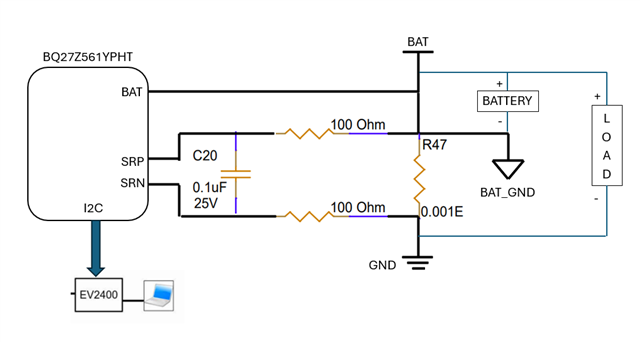
We have used BQ25601D Charger and BQ27Z561 fuel gauge in our custom board.

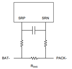
We did POC which is having 12Layer HDI stack up with 1mOhm current sense resistor at fuel gauge side (across SRP and SRN pin). And we are getting proper behaviour/results in terms of Charging current (2A we are setting), Charge Termination, Capacity reading.

Now, Actual board is having 4Layer through hole stack up with same 1mOhm current sense resistor. There are no change in shcematic and BOM between POC and actual board.

And with actual board, we are facing issues mentioned below.

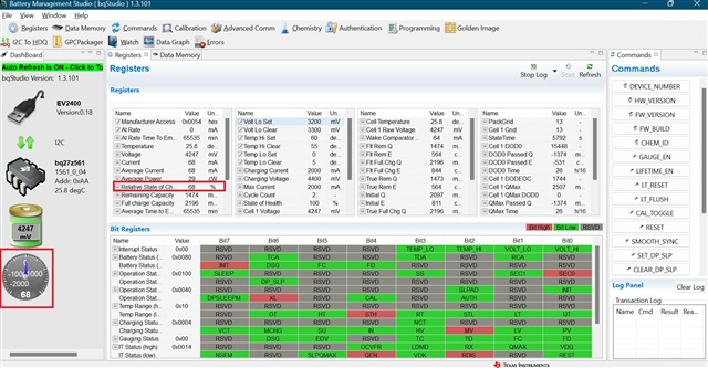
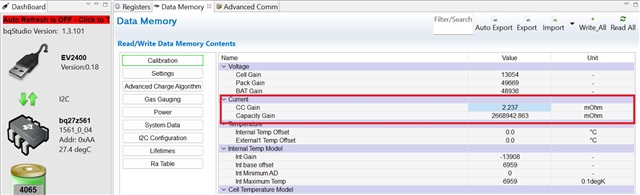
  1.  Charging current read by fuel gauge is 3A even though we are setting the 2A.
  2. We are getting continuous charger interrupt and getting below errors.
  3. After getting many of the below errors, the board will go into not charging state.

-------------------------------------------------------------------------------
[ 709.600214][ C0] i2c_geni 984000.i2c: Bus proto err, noisy/unepxected start/stop
[ 709.608782][ T339] i2c_geni 984000.i2c: i2c error :-71
[ 709.614298][ T339] bq25601-charger 0-006b: Can't read F reg: -71
[ 709.620729][ T339] EIC :: [1553|bq25601_irq_handler_thread]
[ 709.638889][ T3435] i2c_geni 984000.i2c: IO lines in bad state, Power the slave
[ 709.646573][ T3435] [bq27z561] __fg_read_word: Battery not detected, i2c read word fail: can't read from reg 0x2C
[ 709.649400][ T339] i2c_geni 984000.i2c: IO lines in bad state, Power the slave
[ 709.664755][ T339] bq25601-charger 0-006b: Can't read SS reg: -6
[ 709.666022][ T3435] [bq27z561] fg_read_rsoc: Battery not detected, could not read RSOC, ret = -6
[ 709.671214][ T339] EIC :: [1553|bq25601_irq_handler_thread]
[ 709.680255][ T3435] power_supply bms: driver failed to report `capacity' property: -6
[ 709.681206][ T380] i2c_geni 984000.i2c: IO lines in bad state, Power the slave
[ 709.701921][ T380] [bq27z561] __fg_read_word: Battery not detected, i2c read word fail: can't read from reg 0x0A
[ 709.701926][ T380] power_supply bms: driver failed to report `status' property: -6
[ 709.702245][ T339] i2c_geni 984000.i2c: IO lines in bad state, Power the slave
[ 709.702256][ T339] bq25601-charger 0-006b: Can't read SS reg: -6
[ 709.735501][ T380] i2c_geni 984000.i2c: IO lines in bad state, Power the slave
-----------------------------------------------------------------------------------

So, here we have not performed the learning cycle with actual board. We are using the same golden image which is generated with POC board.

Here, is it required to perform the learning cycle with Actual board?

Kindly provide your inputs.

Thanks,

Shivani patel

  • Hello Shivani, 

    You shouldn't have to perform another learning cycle here as long as you are using the same cell that you completed the learning cycle with. It sounds like you will need to recalibrate the gauge though. Please refer to section 12.2 Current Calibration from the bq27z561 TRM

    Regards, 

    Jonny. 

  • Hello Jonny,

    Thank you for your response.


    To clarify the setup for the Current Calibration process, I would like to know if it needs to be done with BQStudio. If so, please confirm whether both the charger and fuel gauge need to be connected to BQStudio, or if only the fuel gauge is required to be connected. I want to ensure clarity on the setup for this calibration.

    Thanks,

    Shivani Patel

  • Hello Shivani, 

    The current calibration can be done through bqStudio. When you are doing the current calibration, you do not need the charger connected.

    Regards, 

    Jonny. 

  • Hello Jonny,


    I have begun the current calibration process by following the steps outlined in Section 12.2 of the bq27z561_trm document.


    I have done the setup as illustrated below.


    Now, I have followed the steps in the following manner.

    1. As instructed in Current Calibration Step 2, I have activated the ManufacturingStatus()[CAL_EN] by utilizing the CAL_TOGGLE command in BQStudio.

    2. In order to send 0xF081 to AltManufacturerAccess(), I clicked on Advance_Comm in BQStudio and wrote the command 81F0 in the Bytes to Write field, as displayed below. Please let me know if this is the correct method for writing commands in the Manufacturer Access System (MAC).

    3. Now, in the 4th step, it is instructed to continuously poll MACData() until the ZZ value increments by 2 before proceeding to read the data.


    Therefore, I attempted to read the MAC Data by clicking on the "Read" button and retrieving 36 bytes of information, as demonstrated below. However, I observed that the data remains unchanged.


    So, at this point, I have several inquiries regarding this particular matter.

    1. I would like to understand the process of polling MACData in BQStudio.
    2. In BQStudio, where can I read the format of the MACData() output, which follows the pattern: ZZYYaaAAbbBBccCCddDDeeEEffFFggGGhhHHiiIIjjJJkkKK as described in Table 11-2 of the Technical Reference Manual (TRM)?
    3. What is the typical duration for performing current calibration?

    Could you please share your insights on this?


    Additionally, is there any documentation available that offers guidance on utilizing BQStudio for the current calibration procedure?
    As the Technical Reference Manual (TRM) does not provide instructions on how to execute the steps using BQStudio.

    Thanks,

    Shivani Patel

  • Hello Shivani, 

    Please refer to this E2E thread as it goes over the I2C communication using bqStudio. I believe this will help with your first and second questions. 

    For your third question, I am not sure what you mean here? For calibrating the current using bqStudio, you should be using the Calibration tab on bqStudio. 

    Regards, 

    Jonny. 

  • Hello Jonny,

    From suggested the E2E thread, it is still unclear how to observe (read/write) the MACData() in BQStudio specifically for the Current Calibration steps.

    Is there any documentation available that provides clarification on the specific steps required to perform Current Calibration in BQStudio?

    Also, do I need to utilize only the Current Calibration tab in BQStudio when performing the Current Calibration process? If so, I couldn't find any option to poll the MACData() as as outlined in Step 4 and 5 of the Current Calibration procedure.

    Regards,

    Shivani Patel

  • Hello Shivani, 

    You can just use bqStudio to calibrate the current using the calibration tab. All you should need to do is input the current that you applied across the gauge in the "Applied Current" section of bqStudio, then click "Calibrate Gas Gauge". One thing to keep in mind here is to use a highly accurate current supplier. 

    Regards, 

    Jonny. 

  • Hello Jonny,

    Thanks for the response.

    SO, are you suggesting that I should only use bqStudio's calibration tab to calibrate the current, and there is no need to follow the Current Calibration Steps mentioned in Section 12.2 of the Bq27z561 TRM?


    Furthermore, could you please provide your insights and answers to the previous queries I had asked?

    1. How to observe (read/write) the MACData() in BQStudio specifically for the Current Calibration steps.
    2. Is there any documentation available that provides clarification on the specific steps required to perform Current Calibration in BQStudio?
    3. I couldn't find any option to poll the MACData() as as outlined in Step 4 and 5 of the Current Calibration procedure.

    Regards,

    Shivani

  • Hey Shivani,

    Today is a holiday and no one is in the office. We will get back to you next week.

    Regards,
    Nick Richards

  • Hello Shivani, 

    Please see the following table for the MACData() taken from the device TRM, and the following E2E thread as it goes over an example of polling the MACData(). You should not have to do this though if you are calibrating using bqStudio, so you can disregard this if you are using bqStudio. Something to note is that when you are using advanced comm, you should ensure that auto refresh is disabled.  

    To use bqStudio to calibrate the current, you will just need to apply a current across SRP and SRN (see the image below), then write this value in the "Current Calibration" section in the Calibration tab of bqStudio (please see the image below). This is all that needs to be done for current calibration in bqStudio. 

    Regards, 

    Jonny. 

  • Hello Jonny,

    Thank you for this detailed clarification.

    To clarify, when using bqStudio for current calibration, should I apply a charge current (positive) or a discharge current (negative) across SRP and SRN?

    Regards,

    Shivani Patel

  • Hello Shivani, 

    You can apply a positive current (charge) across SRP and SRN. 

    Regards, 

    Jonny. 

  • Hello Jonny,

    After successfully calibrating the current using bqStudio, I wanted to verify if the calibration value remains persistent even after powering off the board. Do I need to repeat the current calibration process each time the board is powered on?


    Additionally, in the production when we have a large number of boards to be calibrated, it will be impractical to perform the current calibration using bqStudio on all the boards. Is there other way to handle the current calibration data for all the boards e.g. getting some register settings from bqStudio tool (or some other tool) that can be written in the IC over I2C bus (which will be generic for all the Fuel Guage ICs).

    Regards,

    Shivani Patel

  • Hello Shivani, 

    You do not need to repeat the current calibration process each time the gauge is power cycled. An option for calibrating the gauges during production is to calibrate 20 or so gauges, then to average all the values and program this average value to the gauges during production. 

    Regards, 

    Jonny. 

  • Hello Jonny,

    Okay, understood.

    Now, as you said "An option for calibrating the gauges during production is to calibrate 20 or so gauges, then to average all the values and program this average value to the gauges during production."

    So, which values need to be averaged and how to program these values? Can you please elaborate the exact steps/process for it?

    However, I will get back to you w.r.t Hardware setup validation for current calibration.

    Regards,

    Shivani Patel

  • Hello Shivani, 

    The values that would need to be averaged are the CC Gain and the Capacity Gain values. The exact steps are that you would perform the current calibration using bqStudio on the BQ27Z561. Once the current calibration is complete, you should then record the new value for the CC Gain and the Capacity gain values. You should repeat this process at least 20 more times (with different BQ27Z561 ICs), then average the result. 

    Regards, 

    Jonny. 

  • Hello Jonny,


    After performing the current calibration using two gauges, the current reading (approximately 2A) is accurate according to both fuel gauges.

    However, during the charging cycle with a battery capacity of around 60% and a battery voltage of around 3.8V, the battery status is reported as Full Charged at 89%, which is an unusual result.

    Is this because of current calibration?

    I'm a novice to fuel gauge/charger. So any pointers would really help.

    Thanks,

    Shivani Patel

  • Hello Shivani, 

    Can you provide me with the most up to date gg file and the log file with this behavior? I suspect this is being caused by the parameters you have set for the gauge to detect full charge. 

    Regards, 

    Jonny. 

  • Hello Jonny,

    Please find the attached most up to date gg file and log file for battery status is reporting as Full Charged in between. 

    Please check the below screenshot in which current reduced to 68 mA and Battery capacity showing is 68%. With this charge current battery capacity will not reach to 100%.

    Additionally, I have also being attempting to flash the CC GAIN and CAPACITY GAIN values obtained through Current Calibration in BQSTUDIO. Here is the procedure I followed:

    1. Obtained CC GAIN and CAPACITY GAIN value from BQSTUDIO, which is 1.836.
    2. Converted the value to hexadecimal format following the instructions in BQ27z561 TRM Section: 14.2.3 Floating Point.
    The hexadecimal value obtained is 0x3FEB020C. Is this hex value correct?
    3. Implemented the C logic provided as below to write the values through the fuel gauge driver.

    -------------------------------------------------------------------------
    C Logic:

    //Adding the address
    pData[0] = (unsigned)address & 0xff;
    pData[1] = (unsigned)address >> 8;

    //Adding the data
    pData[2] = (unsigned)value & 0xff;
    pData[3] = (unsigned)value >> 8;
    pData[4] = (unsigned)value >> 16;
    pData[5] = (unsigned)value >> 24;
    cksum = checksum(pData, 6);

    if(gauge_write((void*)&i2cHandle, 0x3e, pData, 6) < 0){
    bq_err("Unable to perform gauge write operation");
    return -1;
    }
    pData[0] = cksum;
    pData[1] = 8; //DATA + CRC

    //Write checksum
    if(gauge_write((void*)&i2cHandle, 0x60, pData, 2) < 0){
    bq_err("Unable to perform gauge write operation");
    return -1;
    }


    -------------------------------------------------------------------------

    In the above logic, first I send the address of data flash which are 0x4006 and 0x400A for CC GAIN and CAPACITY GAIN respectively. Then after I send data in little endian format i.e 1st byte (pData[2]) = 0C, 2nd Byte (pData[3]) = 02,
    3rd Byte (pData[4]) = EB and 4th Byte (pData[5]) = 3F.

    The last two bytes will be the checksum and length. The length in this case will be 8.

    And implementation of the gauge_write function as per given the guidelines in the "A.3 Example Implementation of Gauge APIs for Linux® User Space I²C/dev Interface" section of the Gauge Communication document.


    After successfully flashing the CC GAIN and CAPACITY GAIN values using the above logic, it seems that there is a diffence when reading the values from bqstudio. The CC GAIN value is being read as 2.004, and the CAPACITY GAIN value is 2668942.863 in bqstudio.

    So, what could be the reason of this? Could you please explain?

    It would be helpful to review the custom logic for flashing.

    And if you have any application/C code to write these or any data flash values then please share with me.

    Additionally, when I did current calibration using bqstudio, the updated values of CC GAIN and CAPACITY GAIN were same (1.836)
    However, after flashing these values using the previously mentioned logic, the CAPACITY GAIN value is observed to be significantly different.

    Why the value of CAPACITY GAIN is different?

    We greatly need your for assistance and guidance for further insights to resolving this issue effectively.

    Regards,

    Shivani Patel

    latest.gg.csv

    6648.register_logs.log

  • Hello Shivani, 

    Please expect a delay while I look over what you have sent. 

    Regards, 

    Jonny.

  • Hello Shivani, 

    You should be able to read out the value for the CC Gain using advanced comm that way you do not have to convert from floating point to hex. Are you flashing the CC Gain value to other gauges outside of the one you have calibrated? You will have to calibrate each gauge separately, as the calibrated values very based on the gauge. 

    Regards, 

    Jonny. 

  • Hello Jonny,

    Could you please suggest, how to use advanced comm? Is there any document/reference available for it?

    I am flashing the average value of CC GAIN derived from the calibrated gauges (as you suggested earlier) on non calibrated gauge.

    Also, could you please help on the question which I have asked earlier in my comments:

    ----------------------------------------------------------------------------------------------------------------------

    1. Battery status is reporting as Full Charged in between. Requested gg file logs are attached in previous comment.

    2. After current calibration using bqstudio, the updated values of CC GAIN and CAPACITY GAIN were same (1.836)
    However, after flashing these values using the C logic, the CAPACITY GAIN value is observed to be significantly different. From datasheet, it seems like the range of the data starts from 2.98262E+02. Why the value of CAPACITY GAIN is different here?

    It would be helpful if you provide your inputs on above questions.

    Regards,
    Shivani Patel

  • Hello Shivani, 

    This E2E thread is a helpful thread for how to use advanced comm for the I2C gauges, in this thread Nick goes over an example. It is possible that these values for CC Gain and Capacity Gain were not written correctly to the gauge. 

    Additionally, The values for CC Gain and Capacity Gain should not be the same. Please see the following equations for both values. 

    Using the method I described before, you would be using bqStudio to calibrate at least 20 gauges. You then would average the values for CC Gain, and average the values for capacity gain, then use these averaged values to program to the gauges. 

    Regards, 

    Jonny. 

  • Hello Jonny,

    I referenced the thread you provided and followed the mentioned steps as below.

    1. Write CC_GAIN Address to the MAC Address

    W 0xAA 0x3E 0x06 0x40

    2. Write the new value for CC_GAIN to address 0x40

    W 0xAA 0x40 0x3FEB020C

    3. Calculate the checksum
    0xFF - (0x06 + 0x40 + 0x3F + 0xEB + 0x02 + 0x0C) = 0x7E

    4. Write the checksum to 0x60
    W 0xAA 0x60 0x7E

    5. Write the length to 0x61
    W 0xAA 0x61 0x08
    (Length = 2 address bytes + 4 data byte + 1 checksum byte + 1 length byte)

    Kindly confirm if the steps I followed are correct or not.


    After following the provided instructions, I have encountered a problem where the value of CC_GAIN does not appear to be updated when I try to read it from Data Memory. However, when I read on Advanced_Communication, the value is correctly written. Please check the below Screenshots.

    Data Memory:

    Advanced_Comm:

    I am unsure of the reason behind this. Could you please clarify what could be the reason of this?

    Additionally, I would appreciate clarification on whether the CC_GAIN value should be updated exclusively in Data Memory or it needs to be checked on Advance_Comm only.

    Thanks,

    Shivani Patel

  • Hello Shivani, 

    The CC_GAIN value can be updated either using the Data Memory tab or using advanced comm. With that being said, I believe I have found the issue here with your process. The Calculation for the checksum is incorrect, the checksum should be 0x81 not 0x7E. Additionally, to see the value updated in the Data Memory, please click the "Read All" button in bqStudio. 

    Regards, 

    Jonny. 

  • Hello Jonny,

    I have corrected checksum value and did the same procedure again as shown below. Then tried to read value in Data Memory section by clicking on "Read All" button but still CC_GAIN value is not getting updated in Data memory.

    Could you please help with the above issue?

    Also, could you please answer below question which I have asked earlier in my comments.:

    • Battery status is reporting as Full Charged in between. Requested gg file logs are attached in previous comment. reattaching the logs for this issue.

    Thanks,

    Shivani Patel

    7028.latest.gg.csv7028.register_logs.log

  • Hello Shivani, 

    Please expect a delayed response. 

    Thanks, 

    Jonny. 

  • Hello Jonny,

    Do you have any update to share?

    Thanks,

    Shivani Patel

  • Hello Shivani, 

    Are you able to change the value in the Data Memory window? 

    For your previous question, the FC bit in Battery Status is just a flag that indicates full charge. Please see the conditions below that determine when the FC bit gets set (screenshot is from the TRM). 

    Regards, 

    Jonny. 

  • Hello Jonny,

    Yes, I am able to change the CC_GAIN and CAPACITY_GAIN values from Data Memory window.

    Thanks,

    Shivani Patel

  • Hello Shivani, 

    You do not necessarily need to use Advanced Comm to program the CC Gain to the gauge. What you can do is calibrate at least 20 gauges, then take the average for the CC Gain and Capacity gain, then program this onto a gauge using the Data Memory tab (as previously mentioned). Then, you can use this to create your golden image in the future. The golden image will contain the CC Gain and Capacity Gain values. 

    Regards, 

    Jonny. 

  • Hello Jonny,

    Yes, that's correct. The Data Memory tab allows us to program the CC_GAIN and CAPACITY_GAIN values.
    However, since we already have a golden image in place and the reason to utilize Advanced Comm is that when we try to program these values using the below provided C Program logic (as previously mentioned in my comment) in our driver, there is a difference in the readings obtained from bqstudio. Specifically, bqstudio reads the CC GAIN value as 2.004, and the CAPACITY GAIN value as 2668942.863, whereas the actual value we intend to program is HEX Value 3FEB020C, which is equivalent to 1.836 in float.

    Therefore, you suggested to check the adv comm option of bqstudio and see if it is working. So, based on these results and your suggestion, we need to figure out to ensure the correct programming of these values by using the Advanced Comm feature.

    You can refer the C code logic and code explanation the in the communication of date "17th April 2024".

    The implementation of the gauge_write function of this code is as per given the guidelines in the "A.3 Example Implementation of Gauge APIs for Linux® User Space I²C/dev Interface" section of the Gauge Communication document.

    So, we aim to determine whether the provided logic correctly writes these values or not by using the Advanced Comm feature. This will allow us to verify if the CC_GAIN and CAPACITY_GAIN values are accurately programmed and ensure their correctness.

    I hope, I am able to explain our issue.

    Your comments on this matter would be greatly appreciated.

    Thanks,
    Shivani Patel

  • Hello Shivani, 

    Even if you have a golden image already, you can upload this golden image to a gauge using bqStudio, then manually change the CC_GAIN and CAPACITY_GAIN value in the Data Memory tab, then you can recreate a new golden image with the new CC_GAIN and CAPACITY_GAIN values reflected in the new golden image, along with all of your previously configured parameters. 

    Likely if you are reading the hex values for the CC_GAIN and CAPACITY_GAIN and then trying to convert the hex value to floating point, it is possible that you are making a mistake here in this conversion. This is why I recommend just creating a new golden image with the new CC_GAIN and CAPACITY_GAIN values changed using the Data Memory tab. 

    Regards, 

    Jonny. 

  • Hello Jonny,

    ---
    Even if you have a golden image already, you can upload this golden image to a gauge using bqStudio, then manually change the CC_GAIN and CAPACITY_GAIN value in the Data Memory tab, then you can recreate a new golden image with the new CC_GAIN and CAPACITY_GAIN values reflected in the new golden image, along with all of your previously configured parameters.
    ---

    Queries:
    1. Could you please guide me on the process of uploading a golden image in bqstudio? It would be highly appreciated if you could provide a step-by-step procedure. Additionally, since four golden image files have been generated (bq.fs, gm.fs, df.fs, and srec.fs), kindly advise which file or files need to be uploaded.


    2. What is the process for creating a new golden image? Is it necessary to repeat the entire learning cycle, or are there specific steps to follow e.g. following only charging cycle?


    ----
    Likely if you are reading the hex values for the CC_GAIN and CAPACITY_GAIN and then trying to convert the hex value to floating point, it is possible that you are making a mistake here in this conversion.
    -----


    In order to validate the accuracy of our HEX value, we attempted to read the value in Advanced Comm, which is written through the Data Memory tab. However, we discovered that the value obtained was different. To address this issue, I took the following steps:

    1st Attempt
    1. Write 1.836 value in Data Memory

    2. Upon reading the value in Advanced Comm, we observed a reading of 1.836 to 0x40004763 which is equivalent to 2.004.


    2nd Attempt
    1. Write 1.636 value in Data Memory
    2. Observed a reading of 1.636 to 0x400FF5FD which is equivalent to 2.249.

    Why do the values differ in both cases?

    The similar kind of behavior happening with the C logic (as mentioned previously) we are using to write the CC_GAIN and CAPACITY_GAIN values. When attempting to write the 0x3FEB020C, which is equivalent to 1.836 in float, and then reading the CC GAIN value in bqstudio, it is observed that the value is read as 2.004 in data memory.

    Could you please provide your inputs on this?

    Additionally, would it be feasible to schedule a call at a mutually convenient time to discuss our problem further and expedite process?
    Please note that we are located in the IST time zone.

    Kindly let us know.

    Thanks,

    Shivani Patel

  • Hello Shivani, 

    To upload a golden image using bqStudio, all you need to do is navigate to the "Programming" tab, then select the file location of the golden image you have previously created, then select "Program". 

    To create a new golden image using bqStudio, you just need to locate the "Golden Image" tab, then create the new golden image. You should not have to redo the learning cycle as long as you first upload the old golden image to the gauge. Then change the CC_GAIN and CAPACITY_GAIN value, then create a new golden image.

    Could you please provide your inputs on this?

    How are you converting the hex value to a floating point value? 

    If you use the method I previously described (creating a new golden image), then you do not need to do this process in advanced comm. 

    Regards, 

    Jonny. 

  • Hello Jonny,

    ----

    select the file location of the golden image you have previously created, then select "Program". 

    ---

    Query:

    • Which specific file should I upload: .bq.fs, df.fs, gm.fs, or srec.fs?

    Thanks,

    Shivani Patel

  • Hello Shivani, 

    The bq.fs should be sufficient 

    Regards, 

    Jonny.