This thread has been locked.

If you have a related question, please click the "Ask a related question" button in the top right corner. The newly created question will be automatically linked to this question.

TPS25730: Excess Load Capacitance

Part Number: TPS25730

I am using the TPS25730S in my design. The datasheet says you can only have a maximum of 100uF of capacitance on the VSYS output. I have a larger load in my system that when switched on requires more than 100uF of capacitance to keep my voltage rail stable. You also have a note that says: "USB PD specification for cSnkBulkPd (100µF) is the maximum bulk capacitance allowed on a VBUS sink after a PD contract is in place. The capacitance is sufficient for all power conversion devices deriving power from the PD Controller sink path. For systems requiring greater than 100uF, VBUS surge current limiting is implemented as described in the USB3.2 specification". Is there a recommended solution on how to handle having more than 100uF of capacitance on the VSYS output of the TPS25730S part?
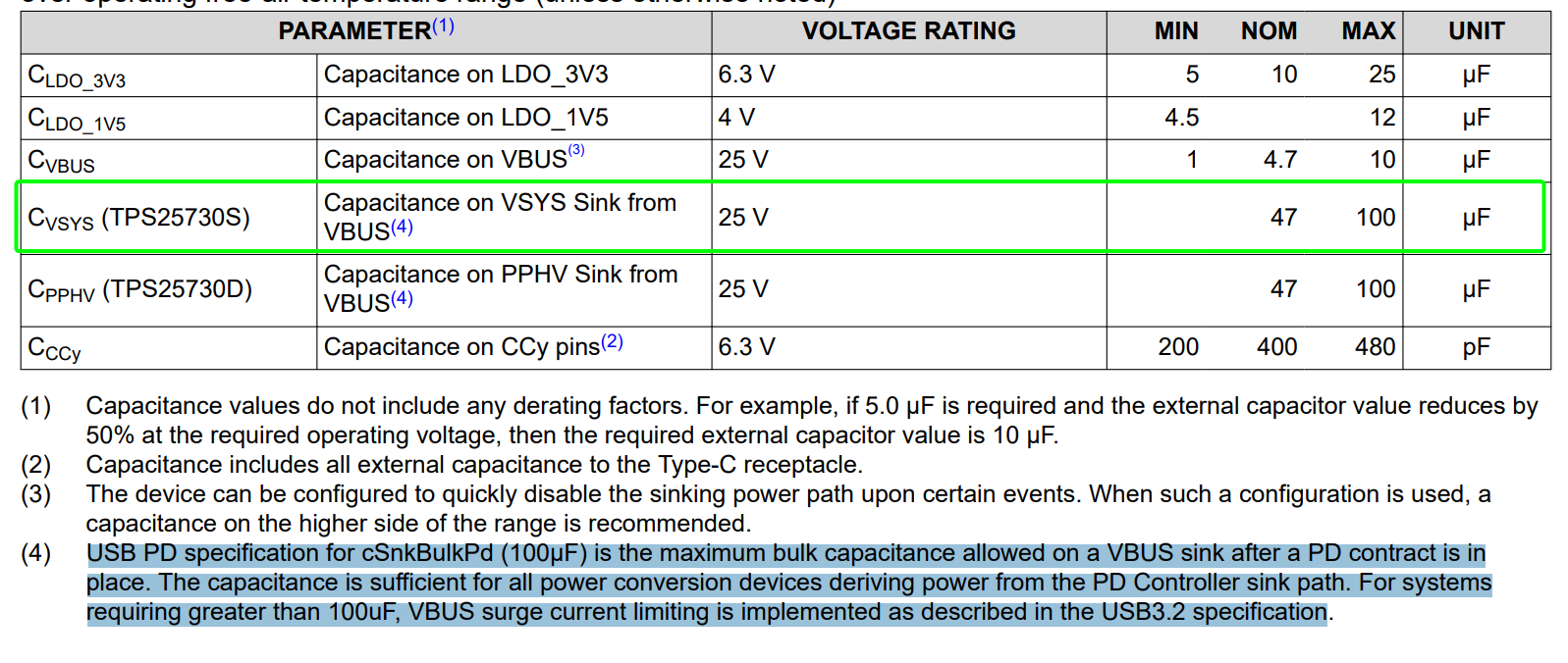
  • One last thought on this topic. The TPS25730S has integrated slew rate control, so that should help with in rush current for larger capacitive loads. Can you provide some background on where this 100uF limitation comes from? I understand USB A and B had limitations on load capacitance for device ports, but don't quite understand if USB C has the same limitations.

  • Hello Brandon,

    The capacitors on VBUS needs to be charged and discharged during VBUS voltage transitions that are supported in USB PD specification. The maximum value of capacitor is specified so that various parameters in the specification are specified after accounting for capacitor charging and discharging. 

    I request you to check section 7.2.2 of USB Power Delivery Specification Revision 3.2, Version 1.0, 2023-10.

    Is there a recommended solution on how to handle having more than 100uF of capacitance on the VSYS output of the TPS25730S part?
    The TPS25730S has integrated slew rate control, so that should help with in rush current for larger capacitive loads.

    Let me check more on above two questions and get back with answers early next week. 

    Thanks and regards,
    Rohit.  

  • Hi Rohit,

    I studied the TPS25730S a bit more. Could I use the "SINK_EN" control pin and a load switch? So maybe I limit the capacitance before the load switch to 100uF, let the USBC negotiate, and then SINK_EN turns on the load switch to a larger capacitive load?

    Thanks,

    Brandon

  • Hi Brandon,

    SINK_EN (active low) control pin levels are synchronous to GATE_VSYS/GATE_VBUS in TPS25730S. Since TPS25730S is a ROM based device with no custom application configuration, I will not be able to change this behavior. 

    USB PD specification at the bottom of table 7-26 "Sink Electrical Parameters" mandates to implement VBUS surge current limiting and points to section 11.4.4.1 of USB3.2 specification  if capacitance more than cSnkBulk max or cSnkBulkPD is required.  

    May I request you to share some details of why the circuit needs more that 100uF at VSYS output? What is the total capacitance value needed? Please also check if there is possibility to limit it within 100uF.  
     
    Thanks and regards,
    Rohit. 

  • Hi Rohit,

    I was able to reduce my total bulk capacitance down to a 47 electrolytic cap and 60uF of ceramic capacitance, so about 100uF total. I think that solves this problem. Thanks for your help navigating the USB-C spec!

    Brandon