


Hi
I have a query need your help.
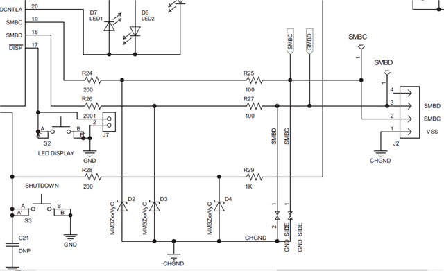
For the BQ40Z50-R1, The typical applications show 300Ω resistors(100Ω+200Ω)in string on SMBC and SMBD. However, for some reason, we use 1KΩ resistor as SMBUS communication external pull-up resistor.
For the 300Ω resistor and 1kΩ external pull-up resistor.,while the BQ40Z50-R1 output data and pulldowm the data line(SMBD),the voltage of SMBD(J2) is close to 1V(.Measurement and analysis judge that there is resistance
inside BQ40Z50-R1). Change R26 and R27 from 200/100 Ω to 10 Ω,the voltage of SMBD(J2) is about 340mV.
Based on these, My question is whether the series resistance on SMBUS can be reduced, for example, R26/R27 can be changed to 10Ω or 0 Ω.? If not, what is the reason for this design—— add series resistance of 100/200.Ω.
Waiting for your reply.
Thanks
Star
