This thread has been locked.

If you have a related question, please click the "Ask a related question" button in the top right corner. The newly created question will be automatically linked to this question.

TPS546D24A: PMBUS programming format

Part Number: TPS546D24A

Hello team,

I need your help to know the right PMBUS programming sequence for this device.

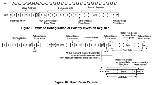
I looked for the figure as the following example (not for TPS546D24A) on the TPS546D24A datasheet but couldn't find..

I had a trouble for both read and write after the Data to Register command. (Confirmed ACK in Slave Address and Command Byte comand.)

I guess that there is something of mismatch on the Data to Register format. Any of your kind advice is highly appreciated.

Thanks in advance.
S.Sawamoto

  •  

    PMBus uses transaction types defined by the SMBus specification, so they are not repeated in the TPS546D24A datasheet.

    http://smbus.org/specs/ 

    The sequence for a Write Transaction is:

    Start Event, 7-bit PMBus address + Wr bit, Command Code, Data Bytes... Stop Event

    For Send Byte transactions like Clear Faults or Store User All, there are no data bytes

    For Write Byte transactions like OPERATION or ON_OFF_CONFIG, there is 1 data byte

    For Write Word transactions like VOUT_COMMAND, there are 2 data bytes, send Low Byte High Byte

    For Write Block transactions like TELEMETRY_CONFIG, the first byte is the Block Count with the number of additional data bytes (Block Count Byte not included)

    The sequence for Read Transactions is similar, except there is a Repeated Start transaction and additional address byte

    Start Event, 7-bit PMBus address + Wr bit, Command Code, Repeated Start, 7-bit PMBus Address + Rd bit, Data Bytes from target, Stop Event

    The data bytes are similar to the Write Data, except there is no reading of Dataless commands like Clear Faults or Store User All

    For the correct data format, see the supported command list or the register maps in the TPS546D24A datasheet.

    It should also be noted that the TPS546D24A makes use of clock stretching, so it is important that the controller supports clock stretching by the target.

    The TPS546D24A also supports the addition of a Packet Error Check (PEC) byte to the end of transactions before the Stop event to detect transmission errors, but does not require PEC to be sent.

  • Hi Peter,

    Thanks for the kind explanation. That can help the user to communicate PMBUS correctly.

    As one additional question, an non-ACK reply observed when we accidentaly try to write invarid data. (For example, we can get ACK in writing 10b on the bit 7:6 (VO_OV_RESP) at 41h, but non-ACK in writhing 11b on it.)

    I'd like to confirm if that is an expected behavior as the design for this device?

    Thanks,

  •  

    As one additional question, an non-ACK reply observed when we accidentaly try to write invarid data. (For example, we can get ACK in writing 10b on the bit 7:6 (VO_OV_RESP) at 41h, but non-ACK in writhing 11b on it.)

    I'd like to confirm if that is an expected behavior as the design for this device?

    Yes.  The TPS546x24y family of devices includes valid data checkers and will NACK invalid data.

    In addition, this will set the IVD (Invalid or Unsupported Data) flag in STATUS_CML and assert SMB_ALERT low to inform the system that invalid data has been received.