


Other Parts Discussed in Thread: TL431, TLV431
Would it be possible to speak to a TI FAE about getting a simulation model for UCC25660 (and hopefully a working simulation of some sample LLC design or reference design that I could use as a starting point)? I think my regular FAE (who'd currently on vacation) said months ago that TI has internal simulations/models of UCC25660 that they could share once my employer had a NDA signed with TI.
My regular FAE is currently on vacation, and I just got the NDA signed and sent on to the TI lawyer that sent it to me and would like to get that simulation model ASAP to help me quickly solve some design/stability issues (if I'm recalling correctly and my FAE was correct about such a simulation model existing).
Here's the question that I want the simulation model to help me figure out for myself, maybe someone can help me without simulations:
I'm working on a non-standard application with UCC25660 (very wide input voltage range, no PFC, relatively low output power compared to the magnetizing current required to maintain ZVS across my operating range and component tolerances) that's forced me to make some unconventional choices in Lm, Lr, and Cr (very low Ln=Lm/Lr ratio of 2-3), and I'm having issues with the control loop stability/bandwidth.
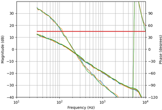
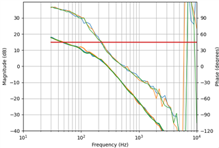
I'm seeing one consistent Bode plot at light load and a very different but still consistent Bode plot at high power, with the power that counts as 'low' vs 'high' changing with my input voltage. The switching frequency is below the Lr-Cr resonant frequency for all of these situations (my prototype MgMin > 1). The high power response is less stable, with lower gain but a much lower frequency of hitting 0 degrees measured in-loop before extending all the way down to -180 degrees.
I'm only able to compensate with a crossover frequency of around 150-200Hz, and in some transient conditions my opto current increases past Ifb long enough that UCC25660 increases the switching frequency so much that the magnetizing current collapses and the device enters hard switching. (I have burst mode currently disabled because of other issues with my wide input range, but when I had it enabled accidentally, even HF burst mode gave very bad looking waveforms with lots of hard switching.) I've attached my uncompensated (Type I) Bode plots that I've used as basis for designing my Type 2 or Type 3 compensation networks.
Also, with the highest TSET option that gives me some safety margin to my minimum switching frequency, I'm sometimes seeing instability at startup and load transients that reminds me of subharmonic oscillation: the output duty cycle is nowhere near 50%, with ISNS spiking much higher for a shorter duration for one half of the cycle and lower for a longer duration for the other half of the cycle. This happens at both lower frequencies during startup and higher frequencies when I decrease the output current. Changing TSET from #3 to #1 makes these asymmetries go away, but it also means that my full scale range of output power is achieved over a range of opto current from only 55-62 uA.
I'm guessing that UCC25660's VCR synthesizer and Vth ramp act as a sort of ramp compensation to prevent subharmonic oscillation and the ramp rate with TSET based on my switching frequency was insufficient for my set of parameters.
I've already tried TI's UCC25660x_CALC_1.0.xlsx spreadsheet, but it doesn't make any suggestions about stability/bandwidth and doesn't seem to account for component tolerances. I can choose input values that make it successfully recommend the design I'm currently using, but I selected my current design based on Python simulations I wrote that take both my operating range and Lm, Lr, Cr tolerances into account (but all based on the first harmonic approximation), and it looks like TI's spreadsheet can't automatically consider the changes to Mg across component tolerances, considering how the spreadsheet makes you update the graph to match your selected components.
Does anyone know what factors influence the uncompensated (type 1) frequency response of a UCC25660 flyback, or why I'm getting two very different Bode plots depending on the power level?
