This thread has been locked.

If you have a related question, please click the "Ask a related question" button in the top right corner. The newly created question will be automatically linked to this question.

TPS768: Testing output current limitation of TPS76801QD

Part Number: TPS768


Hello.

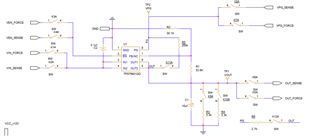
After I test the output current limit of TPS768Q1D, I found it was broken. It couldn't operate normally.I set the source voltage 4.3V and current 1A.Then I test the output current .By the way ,I chose resistors vauled 30.1K and 53.6K so that its output voltage value can reach 3.3V. After testing the output current limit, I found it couldn't output 3.3V.

Perhaps there was false in my method. Should I set the source voltage 0V to cater the condition that output voltage is zero?What the right way to test output current limit?

Thanks for you answer.

  • Hello, 

    TPS768 has internal current limiting, output current is limited to approximately 1.7A, in an overcurrent situation, output voltage will scale back until overcurrent protection ends.

    It is possible that the conditions for this test caused the device to overheat. The maximum junction temperature (TJ max)  TPS768 can operate at is 125°C. Here is the equation for maximum power dissipation of an LDO:

    TA is ambient temperature, assume 25°C. RΘJA is thermal resistance in °C/W, 172°C/W  is the thermal resistance for the D package for this device.  Thermal resistance and recommended operating temperature in this scenario gives us: PD Max = 125 - 25 / 172, PD Max ≅ 0.6

    You can calculate power dissipation (PD Max) with voltage differential between input and output * current, in this case (4.3-3.3)*1 = 1 Watt

    Are you able to share your schematic? 

    BR, 

    Erin 

  • Hello Erin,

    I approximately know the reason that the device had been broken.But I still unclear about the method to test the output current limit.

    According to the calculation, the power disdipation can't beyond 0.6.Additionallly, the lowest value of output current limit is 1.2A and the test conditon is that VOUT=0V.

    Therefore, the input voltage shouldn't beyond 0.5V.However, the device can't operate normally in this case.

    The follow picture is  my schematic.

    The schematic is based on Kelvin Four-terminal Sensing.When test output current limit, I turn on the K1,K2,K3,K4,K5,K6,K11.Las time, I set VIN=4.3V, VEN=0, and test output current.Finally the device broke.

    I really want to know how to test output current limit using my circuit.

    Thank you for your answer.